A-1
Scanner
®
2000 microEFM Appendix A
Appendix A—Scanner 2000 Hardware Options
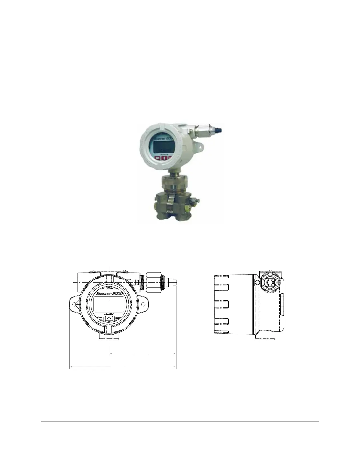
Explosion-Proof Control Switch
An alternative to the automatic scroll display of parameters on the LCD, an external explosion-proof control
switch (Figure A.1) allows the user to manually select which parameter is displayed on the LCD and view
daily logs instantaneously without removing the instrument cover or connecting the instrument to a laptop
computer. The switch is available in both a CSA-approved model for use in Div. 1 or Div. 2 installations (9A-
30054001), and an ATEX-approved model for Zone 1 installations (9A-30054002).
Figure A.1—Explosion-proof control switch
The switch mounts in either threaded conduit opening in the instrument housing. If both network
communications and an RTD are required, a small junction box must be installed to establish a third conduit
connection location.
4.87
(123.6)
7.72
(196.1)
Figure A.2—Dimensions of explosion-proof control switch; inches (mm)
If the switch is ordered with a Scanner 2000 microEFM, it will be installed prior to shipment. To add a switch
to an existing Scanner 2000, terminate the leads to connector J2 on the main circuit board (Figure A.3).