54
Section 2 Scanner
®
2000 microEFM
Measuring Uncompensated Liquid via a Turbine Meter
Best Practices
The Scanner 2000 microEFM calculates uncompensated liquid ow through a turbine meter in accordance
with API MPMS, Chapter 5, Section 3, Measurement of Liquid Hydrocarbons by Turbine Meters. For
optimum performance, ensure that the turbine and Scanner 2000 installation complies with the industry
recommendations listed below:
• Install the turbine owmeter in the meter run such that there are at least 10 nominal pipe diameters up-
stream and ve nominal pipe diameters downstream of the meter. Both inlet and outlet pipe should be of
the same nominal size as the meter.
• Straightening vanes are recommended for eliminating swirl conditions. If used, they should be installed
ve pipe diameters upstream of the meter.
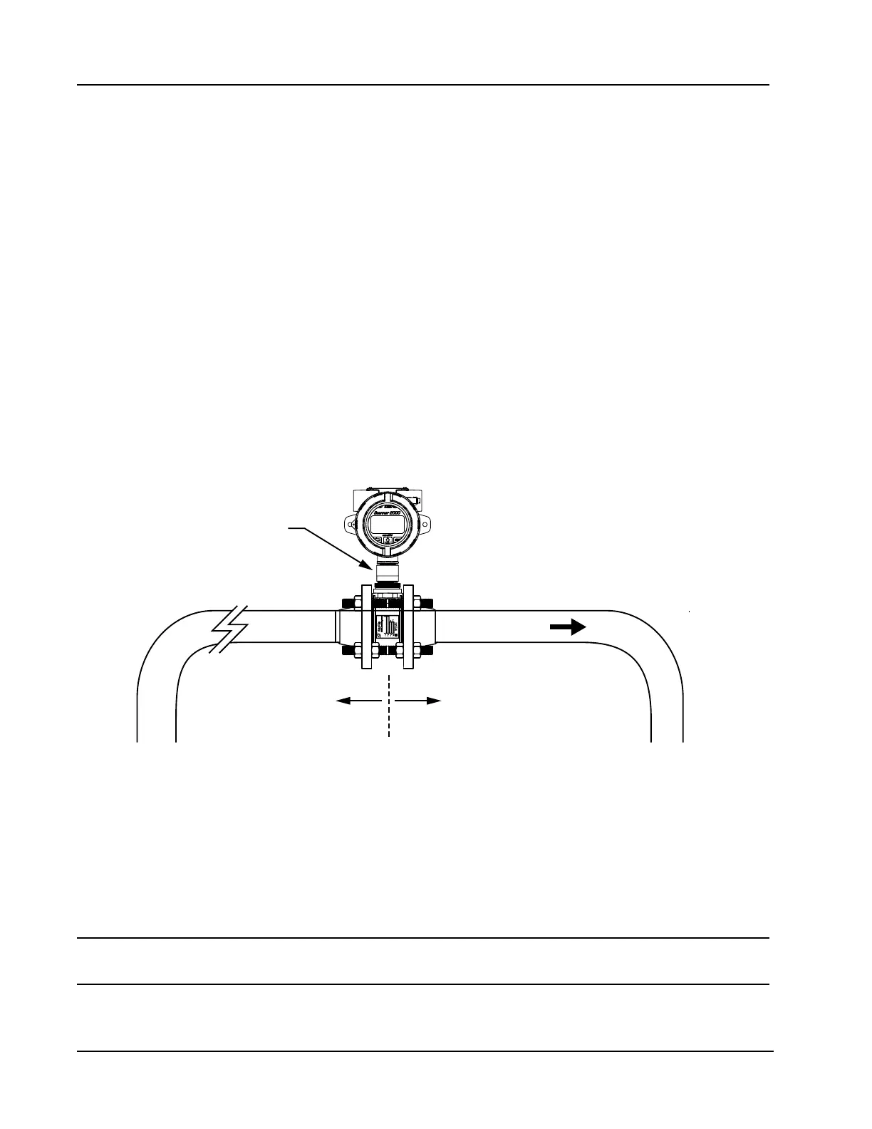
Installation Procedure—Direct Mount to a Turbine Meter (CSA Compliant)
A Scanner 2000 without the MVT bottomworks can be mounted directly to a liquid turbine meter for
measuring liquid (Figure 2.14). A pipe adapter and union are attached to the Scanner, allowing a direct
connection to the turbine meter.
Flow
Adapter/union
(CSA-approved)
10 pipe diameters
upstream (minimum)
5 pipe diameters
downstream (minimum)
Figure 2.14—Direct-mount installation for use with a Barton 7000 Series meter
To connect the Scanner 2000 to a liquid turbine meter using this method, perform the following steps:
1. Position the Scanner 2000 above the owmeter.
2. Plug the Scanner 2000 cable connector into the magnetic pickup of the turbine meter and hand-tighten the
knurled nut on the connector.
3. Screw the Scanner 2000 onto the owmeter threads surrounding the magnetic pickup with the display fac-
ing the desired direction.
CAUTION Do not use Teon
®
tape on the threads of the union, adapter, or pipe plugs. Use of
Teon
®
tape will void the explosion-proof rating of the instrument.
4. Tighten all sections of the pipe union.