D-34
Appendix D Scanner
®
2000 microEFM
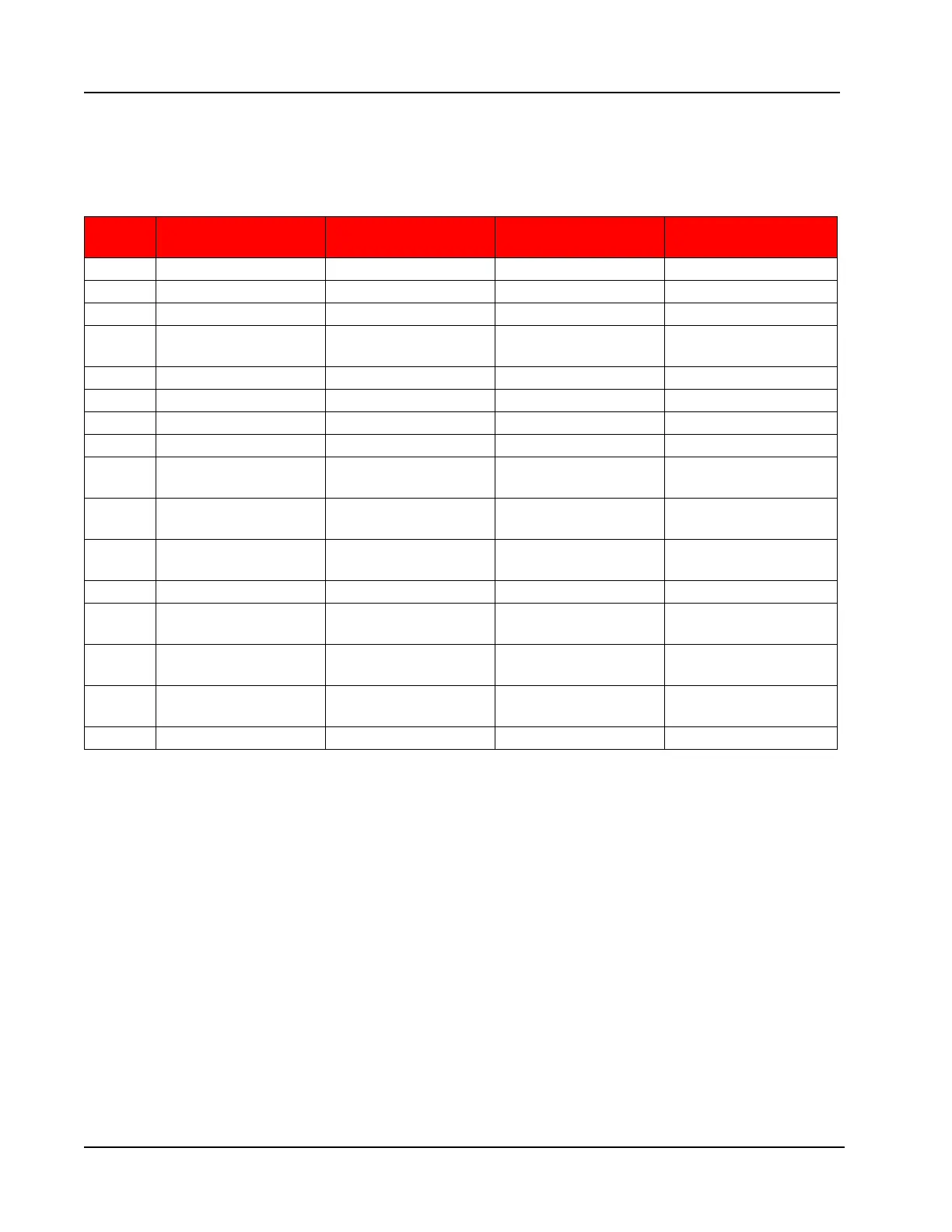
Flow Calculation Parameter Registers (1-16)
The Flow Calculation Parameter Registers denition is dependent upon the ow rate calculation method
that is implemented. The following table describes the function of each of these registers for each of the
supported calculation methods.
Reg.
Num AGA-3 ISO-5167
Cone –Spool
Cone -Wafer AGA-7
1 Pipe Size (Corrected) Pipe Size (Corrected) Pipe Size (Corrected) Pipe Size (Corrected)
2 Plate Size (Corrected) Plate Size (Corrected) Plate Size (Corrected) Temperature Ratio
3 Beta (Corrected) Beta (Corrected) Beta (Corrected) Pressure Ratio
4
Plate Size
(congured)
Plate Size
(congured)
Plate Size
(congured)
Supercompressibilty
5 Stability Index Stability Index Stability Index <Reserved>
6 Y Y Y <Reserved>
7 Cd Cd Cd <Reserved>
8 Ev Ev Ev <Reserved>
9
Flow Extension
(sqrt["H20*lbm/cf3])
Flow Extension
(sqrt[pa*kg/m3])
Flow Extension
(sqrt[pa*kg/m3])
<Reserved>
10
Flowing Density
(kg/m3)
Flowing Density
(kg/m3)
Flowing Density
(kg/m3)
Flowing Density
(kg/m3)
11
Quality (Vapor Liquid
Fraction)
Quality (Vapor Liquid
Fraction)
Quality (Vapor Liquid
Fraction)
<Reserved>
12 Liquid Heating Value Liquid Heating Value Liquid Heating Value <Reserved>
13
Liquid Flowing
Density
Liquid Flowing
Density
Liquid Flowing
Density
<Reserved>
14
Estimated Liquid
Mass Flow Rate
Estimated Liquid
Mass Flow Rate
Estimated Liquid
Mass Flow Rate
<Reserved>
15
Apparent Mass Flow
Rate
Apparent Mass Flow
Rate
Apparent Mass Flow
Rate
Apparent Mass Flow
Rate
16 Lockhart-Martinelli Lockhart-Martinelli Lockhart-Martinelli <Reserved>
Base Units/Congured Units
The holding registers allow users to read data in terms of congured units of measurement and base units. The
congured units follow the settings based on the Unit setting register and the unit scale and offset registers.
The base units will always have the same unit of measurement independent of the unit, scale and offset
settings. Also note that the log data is always in terms of base units. It is recommended to congure the units
of measurement using the software.
Polling Registers
The Scanner 2000 stores volumes, averaged values, and ow times since the last polling sequence in a set of
polling registers. Additionally, the instrument stores the number of polls requested in the polling index.
The polling sequence is started by writing a value of 20,000 to the Control Register. This transfers the polling
totals, averages, and run times to the previous polling registers, increments the polling index and resets the
polling totals, averages and run-time registers. Note that the polling registers are displayed in base units and
congured units.