40
Section 2 Scanner
®
2000 microEFM
Installation Procedure—Direct Mount to a Turbine Meter (CSA Compliant)
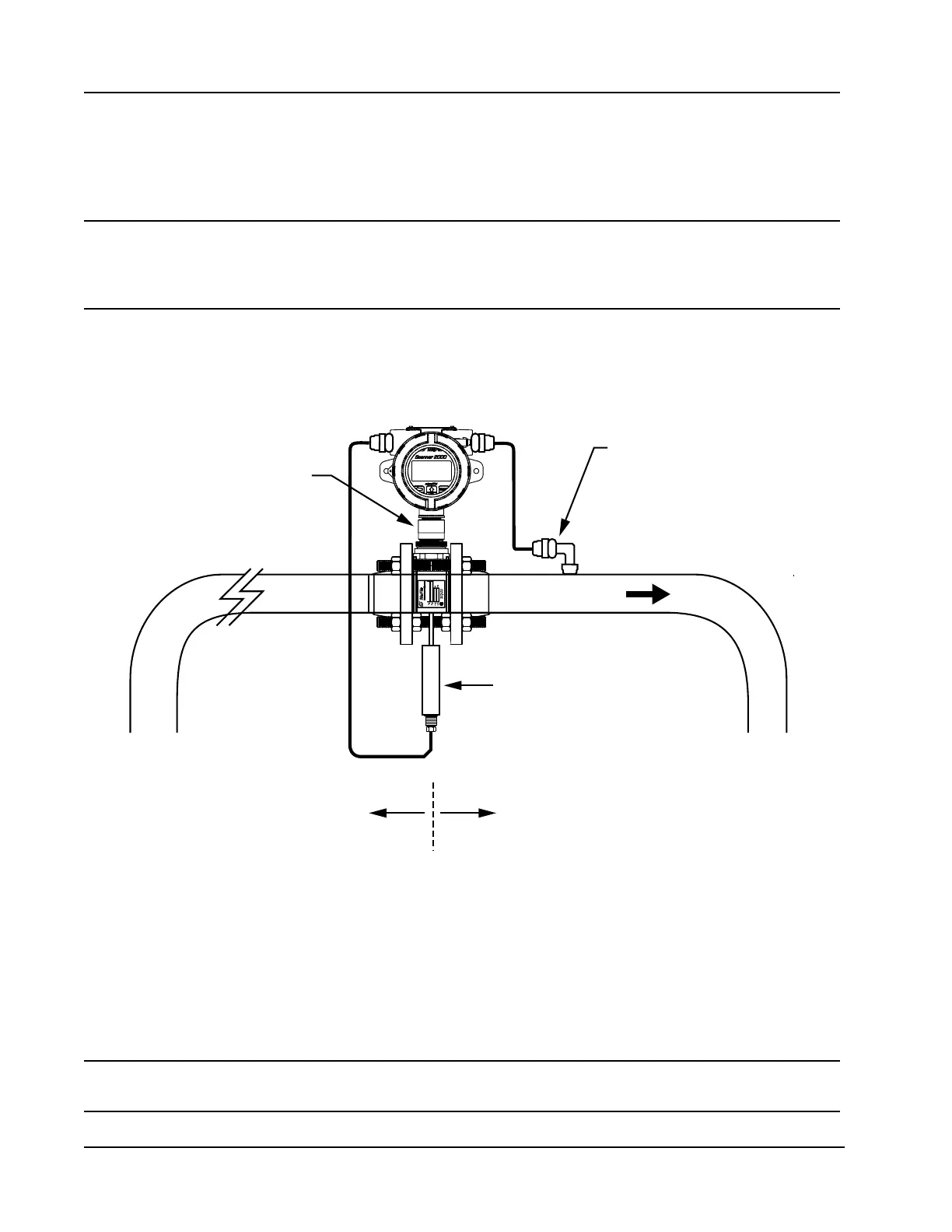
A Scanner 2000 without the MVT bottomworks can be mounted directly to a gas turbine meter for measuring
natural gas. A pipe adapter and union are attached to the Scanner, allowing a direct connection to the turbine
meter.
WARNING HAZARDOUS AREA USE. The Scanner 2000 is certied for hazardous area use only when
installed in accordance with applicable standards and local wiring practices. Carefully
review Hazardous Area Installations, page 27, to determine specic installation require-
ments (cable glands, conduit seals, signal cable, RTD, etc.).
An external pressure transducer is required for converting the pressure to a 4-20 mA or 1-5V signal, and the
Scanner 2000 must be equipped with the optional expansion board, which provides the analog input necessary
to receive the pressure signal from the transducer. If installed in a Div. 1 hazardous area, the transducer must
be explosion-proof.
Flow
Adapter/union
(CSA-approved)
RTD assembly
10 pipe diameters
upstream (minimum)
5 pipe diameters
downstream (minimum)
External pressure transducer
(connected to meter
pressure port)
Figure 2.8—Direct-mount installation for use with a gas turbine meter
To connect the Scanner 2000 to a turbine meter using this method, perform the following steps:
1. Position the Scanner 2000 above the gas turbine owmeter.
2. Plug the Scanner 2000 cable connector into the magnetic pickup of the turbine meter and hand-tighten the
knurled nut on the connector.
3. Screw the Scanner 2000 onto the owmeter threads surrounding the magnetic pickup with the display fac-
ing the desired direction.
CAUTION Do not use Teon
®
tape on the threads of the union, adapter, or pipe plugs. Use of
Teon
®
tape will void the explosion-proof rating of the instrument.