39
Scanner
®
2000 microEFM Section 2
5. Remove the plug from the conduit opening in the top of the Scanner 2000 enclosure, route the turbine sig-
nal cable through the opening, and connect it to the main circuit board. A wiring diagram for the turbine
input is provided in Figure 3.4, page 65. For hazardous areas, review Hazardous Area Installations, page 27.
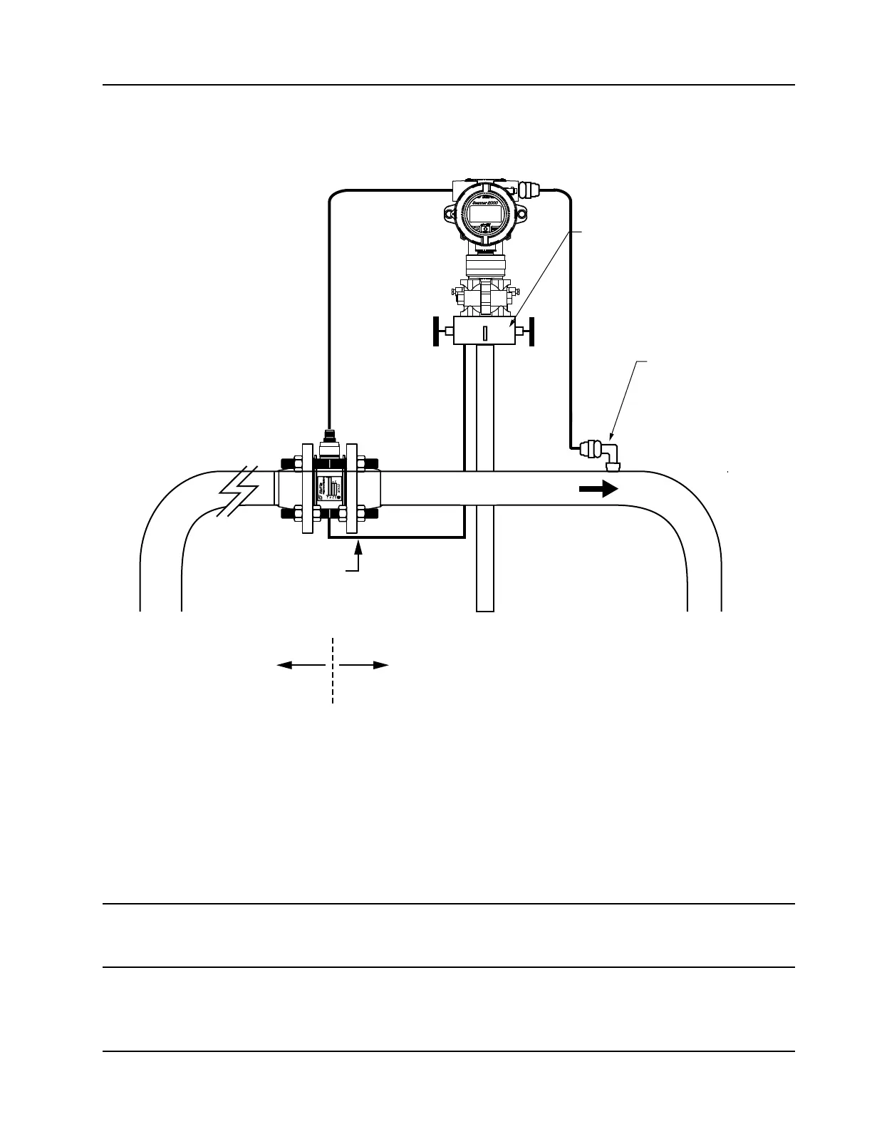
Flow
Manifold
Static pressure input
(manifold equalizer valve
must remain open)
H
L
RTD assembly
10 pipe diameters
upstream
5 pipe diameters
downstream
Figure 2.7—Remote-mount installation in an AGA-7 turbine meter run
6. Install the RTD assembly in the thermowell. Remove the plug from the other conduit opening in the top
of the Scanner 2000 enclosure, route the RTD assembly cable through the conduit opening in the top of
the Scanner 2000, and connect it to the main circuit board. A wiring diagram for the RTD assembly is
provided in Figure 3.5, page 66. For hazardous areas, review Hazardous Area Installations, page 27.
7. Zero the static pressure and recalibrate the static pressure, if required. See the ModWorX™ Pro Software
User Manual, Part No. 9A-30165025, for complete instructions. See also Zero Offset (Static Pressure or
Differential Pressure), page 56, and Static Pressure Calibration and Verication, page 56.
CAUTION Do not put the Scanner into operation until the valves are positioned properly so that
pressure is supplied to both sides of the MVT. For instructions on proper valve positions,
see Placing the Scanner into Operation, page 58.