C-4
Appendix C Scanner
®
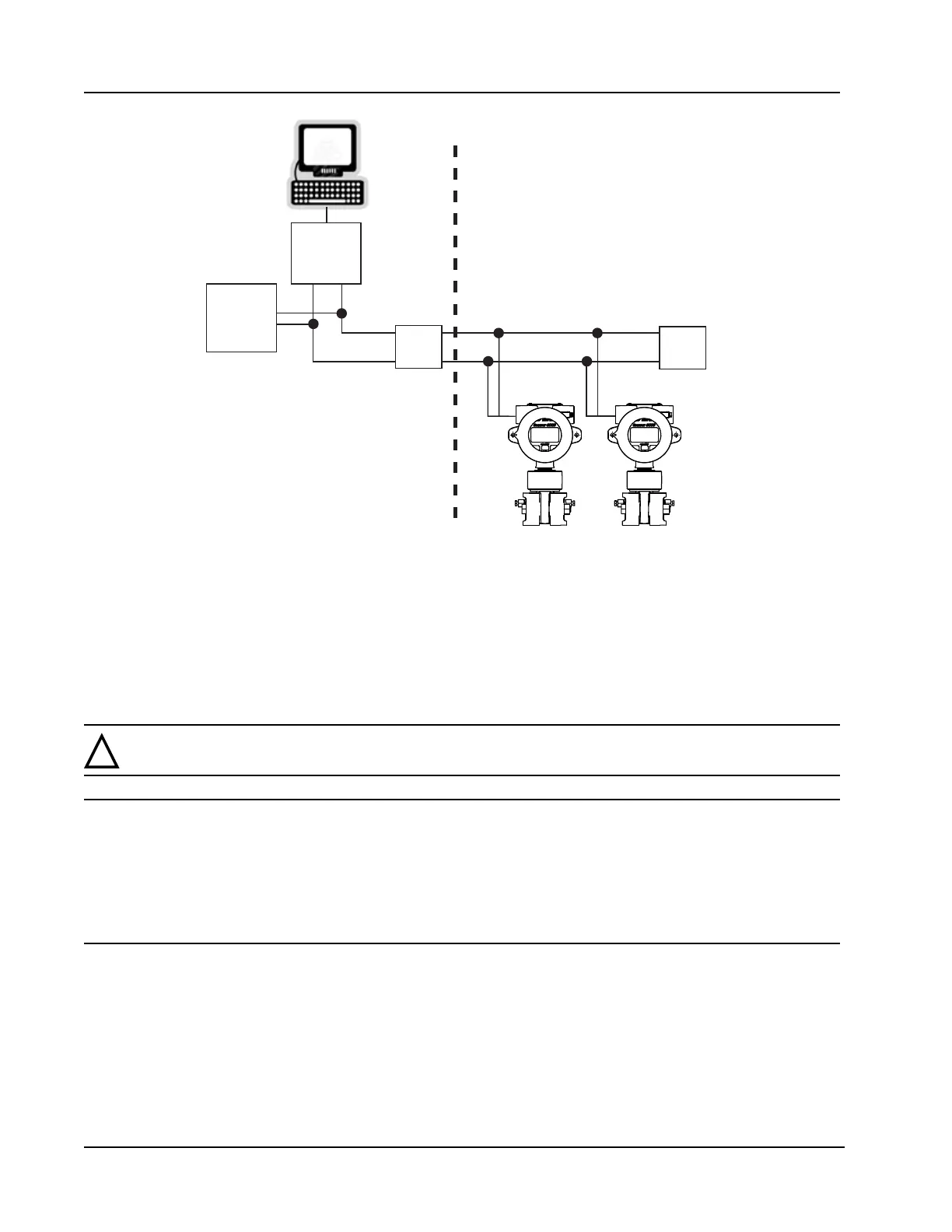
2000 microEFM
HOST
SAFE AREA
HAZARDOUS AREA
TERM
TERM
POWER
SUPPLY
LINKING
DEVICE
Figure C.2—Basic installation
Mounting Options
For instructions on mounting the Scanner 2000, see Mounting Options, page 30.
Field Wiring Connections
!
WARNING: To prevent ignition of hazardous atmospheres, do not remove the cover while cir-
cuits are alive. The Scanner 2000 poses no hazard when opened in a safe area.
CAUTION All eld wiring must conform to the National Electrical Code, NFPA 70, Article 501-4(b)
for installations within the United States or the Canadian Electric Code for installations
within Canada. Local wiring ordinances may also apply. All eld wiring must be rated for
temperatures of 90°C or higher, and have a wire range of 22 to 14 AWG. Terminal block
screws must be tightened to a minimum torque of 5 to 7 in-lbs. to secure the wiring
within the terminal block. Only personnel who are experienced with eld wiring should
perform these procedures.
The Scanner 2000 is bus-powered by a two-conductor eldbus cable that provides both power and
communications. A Scanner may be added to the network or removed from the network while the bus is
running.
Field wiring is connected to two integral circuit boards inside the Scanner 2000.
• The main board includes terminals for a communications port, a turbine input, a process temperature
(RTD) input, a digital output, and a lithium battery connector (for backup power). Use only the Model 21
explosion-proof RTD or equivalent.