A-10
Appendix A Scanner
®
2000 microEFM
Wiring Diagrams
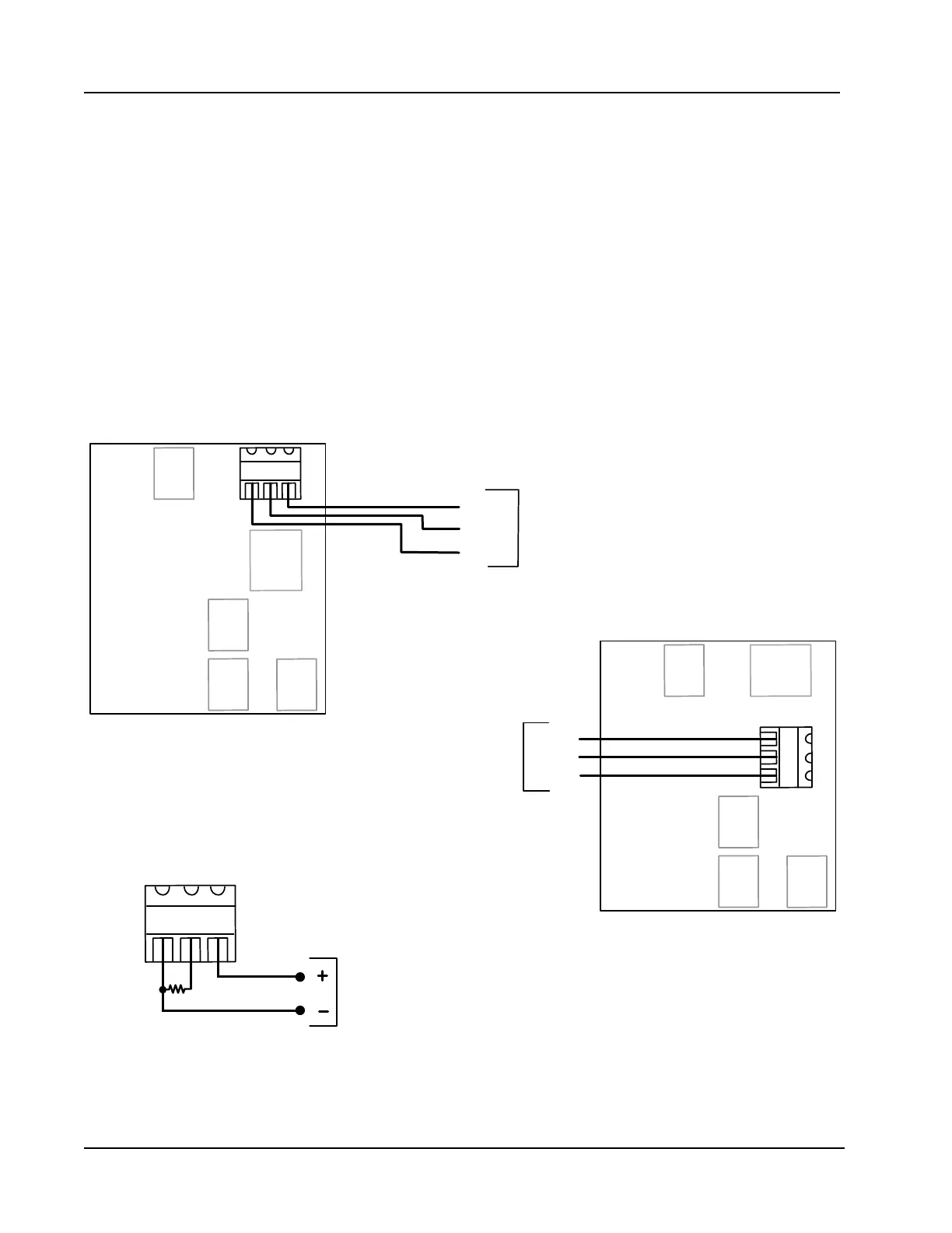
Analog Inputs 1 and 2
The analog inputs, which can be congured for a 0-5 V, 1-5 V or 4-20 mA signal, can be used to receive
readings from a pressure or temperature transmitter for use in AGA-7 gas calculations. Alternatively, they can
be used to log measurements from any device with a 0-5 V, 1-5 V or 4-20 mA output.
Transmitter power is provided by the Scanner 2000 only when the Scanner is externally powered. The output
voltage equals the input voltage less 0.25 VDC, and is limited to 20 mA.
If a 4-20 mA transmitter is used, a resistor must be added to the circuit, as shown in Figure A.15. The
expansion board circuit will support a resistor range of 200 to 300 ohms; 250 ohms is recommended.
ANALOG INPUT 1 (TB5)
17 18 19
TB9
TB8 TB7
TB6
TB5
1-5 VDC
TRANSMITTER
POWER
RETURN
SIGNAL
PWRIN+ IN-
TB4
Expansion
Board PN:
9A-30160014
ANALOG INPUT 2 (TB6)
20
21
TB9
TB8 TB7
TB6
TB5
PWRIN+ IN-
22
1-5 VDC
TRANSMITTER
POWER
RETURN
SIGNAL
TB4
Expansion
Board PN:
9A-30160014
4-20 mA
TRANSMITTER
Resistor Required
(250-ohm recommended)
17 18 19
PWRIN+ IN-
TB5
4-20 mA TRANSMITTER WIRING
(CAN BE USED WITH ANALOG INPUT 1 OR 2)
Figure A.15—0-5 V, 1-5 V and 4-20 mA analog input wiring