A-11
Scanner
®
2000 microEFM Appendix A
Pulse Input
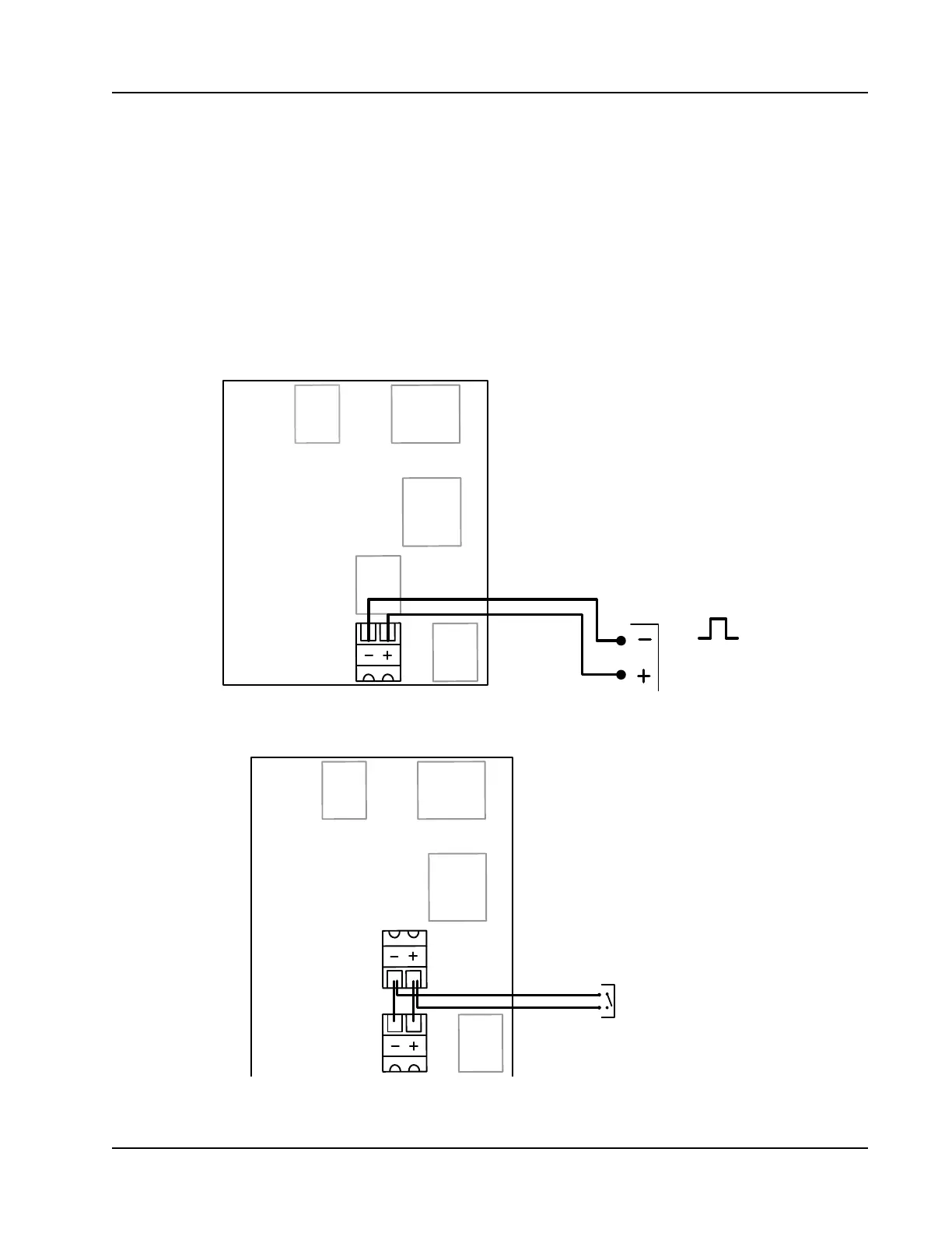
The pulse input provides an optically isolated input for high-amplitude pulse (frequency) signals, which
includes signals from a turbine meter equipped with a preamplier (Figure A.16, top diagram) or signals from
a positive displacement meter (Figure A.16, bottom diagram).
The Scanner 2000 can calculate ow from no more than two pulse (frequency) inputs at a time. Therefore, a
pulse input can be used simultaneously with only one turbine input (main board or expansion board).
The pulse input can also be used as a status input for monitoring a parameter via Modbus
®
registers. See Pulse
Input for Status Indication, page D-25, for details.
25 26
TB9
TB8 TB7
TB6
TB4
TB5
PULSE INPUT
3 TO 30 VDC
PULSE INPUT (TB8)
Expansion
Board PN:
9A-30160014
25
24
26
23
SWITCH CLOSURE
TB9
TB8 TB7
TB6
TB4
TB5
PULSE INPUT/SWITCH (TB7 &TB8)
TB7 AND TB8 ARE CONNECTED BY JUMPER;
TB7 IS THEN WIRED TO THE SWITCH.
Expansion
Board PN:
9A-30160014
Figure A.16—Pulse input wiring