C-2
Appendix C Scanner
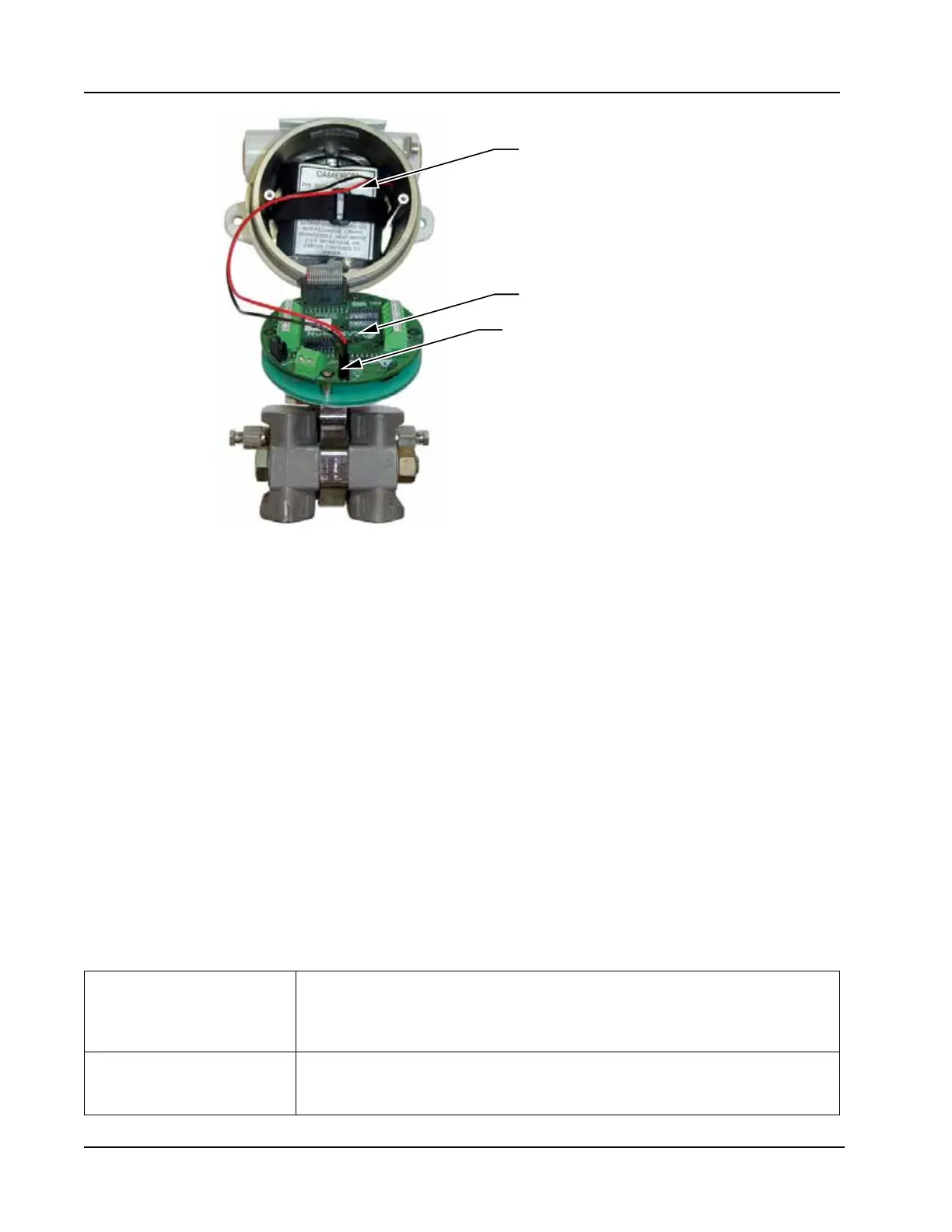
®
2000 microEFM
Lithium battery pack
(double D cell), secured
by a velcro strap
Main circuit board
Battery connector
Figure C.1— Scanner 2000 microEFM, internal view
Hardware Options
Several hardware options are available for customizing the Scanner 2000 to a user’s specic needs. They
include:
• communications adapter for enabling a quick connection to a laptop computer (RS-485 or USB connec-
tor)
• explosion-proof control switch for viewing daily logs with the press of a button and selecting the param-
eter displayed without removing the cover of the Scanner or connecting a laptop
• pole-mounting kit for mounting the Scanner 2000 to a 2-in. pole
• terminal housing that expands the number of input cables that can be connected to the Scanner 2000
See Appendix A—Scanner 2000 Hardware Options, for details.
Specications
Table C.1 contains specications that are specic to Foundation™ eldbus devices. See Table 1.1—Scanner
2000 microEFM Specications, page 15 for all other specications.
Table C.1—Scanner 2000 microEFM Specications (Fieldbus Devices Only)
System Power Fieldbus power supply
• Connects to eldbus interface board
• Device current consumption: 26 mA
Integral battery pack for backup power, 2 “D” batteries in series, 7.2V, lithium
Communications Port One RS-485 communications port on main board
• 300 to 38.4K baud
• Accessed via external communications connector