65
Scanner
®
2000 microEFM Section 3
Input Wiring
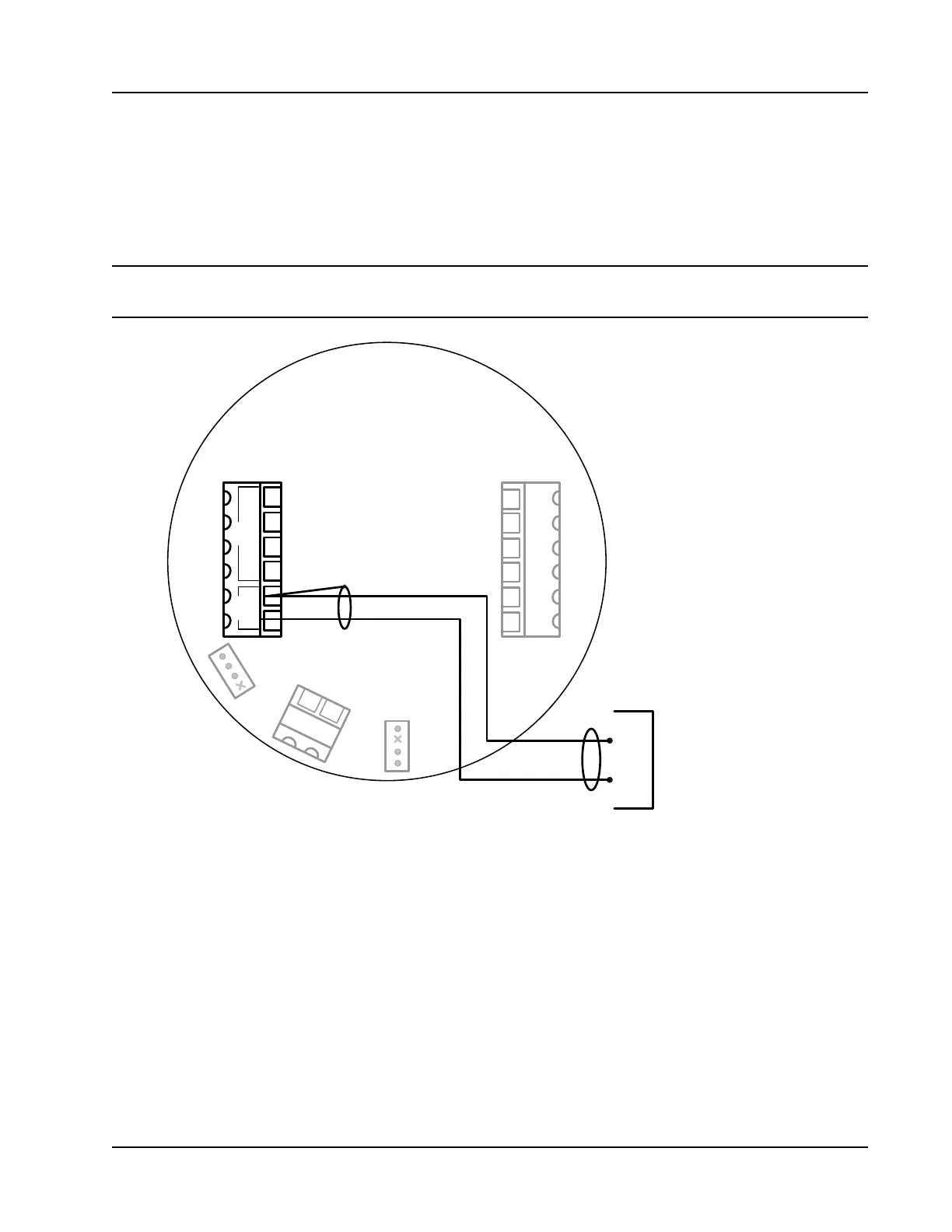
Turbine Flowmeter Input
The Turbine Input 1 on the main circuit board provides the turbine owmeter input signal generated
by a magnetic pickup, enabling the Scanner 2000 to calculate and display instantaneous ow rates and
accumulated totals. Wire as shown in Figure 3.4.
Note If the expansion board option is installed, a second turbine input is available. See Figure A.17, page A-12,
for Turbine Input 2 wiring instructions.
TURBINE
MAGNETIC PICKUP
A
B
TB1 TB2
POWER
TFM 1 RTD
–
+
PORT 2 PORT 1
–
I
+
+
R
+
R
-
I
-
SCANNER 2000
Main Circuit Board
PN: 9A-30160010
J1
TB3
BATTERY
13
14
J2
2
3
4
5
6
1
7
8
9
10
11
12
SWITCH
DIG OUT 1
–
+
–
+
Figure 3.4—Flowmeter input wiring