A-2
Appendix A Scanner
®
2000 microEFM
SWITCH
J1
TB1
BATTERY
13
14
J2
SCANNER 2000
Main Circuit Board
PN: 9A-30160010
TFM 1 RTD
I
+
R
+
R
-
I
-–
+
2
3
4
5
6
1
POWER
PORT 2
PORT 1
–
+
–
+
–
+
7
8
9
10
11
12
TB2
TB3
DIG OUT 1
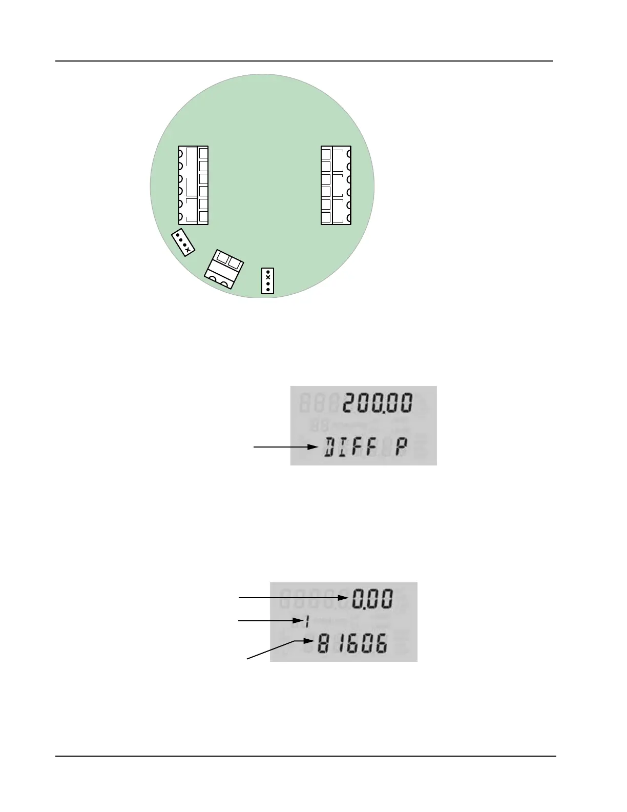
Figure A.3—Wiring of explosion-proof control switch
To select a display parameter for viewing, press and release the push-button switch. With each subsequent press
of the switch, the LCD will display a new parameter (Figure A.4). Parameters will appear in the order specied
by the user when he congured the display. If the user does not press the button to manually advance to the
next parameter, each parameter will be displayed for 30 seconds before the LCD resumes its automatic scroll.
Parameter changes
when push-button
switch is pressed
Figure A.4—LCD display of real-time measurements
To access daily logs, press and hold the push-button switch for approximately 4 seconds. In the daily log
viewing mode, the LCD will display the daily volume recorded (at the top), the date stamp (bottom), and a
two-digit index that indicates the number of days since the log was created (Figure A.5). When you enter this
mode, the LCD automatically displays the daily log value from the previous day, which is marked by an index
value of “01.”
Log index
(Days since log
was created)
Volume
Date stamp
(MMDDYY)
Figure A.5—LCD display of daily logs
To view logs recorded prior to this date, press the push-button switch repeatedly. The index number will
increase in value (02, 03, etc.) as the logs progress back in time, and the corresponding daily log volumes and