D-4
Appendix D Scanner
®
2000 microEFM
Map Starting Register
User-Dened Holding Registers 9100
Device Status 9900
Note: All registers cited in this document refer to the address of the register that appears in the actual
Modbus® message. For example, register 8000 has an address of 0x1F40 hexadecimal in the
message.
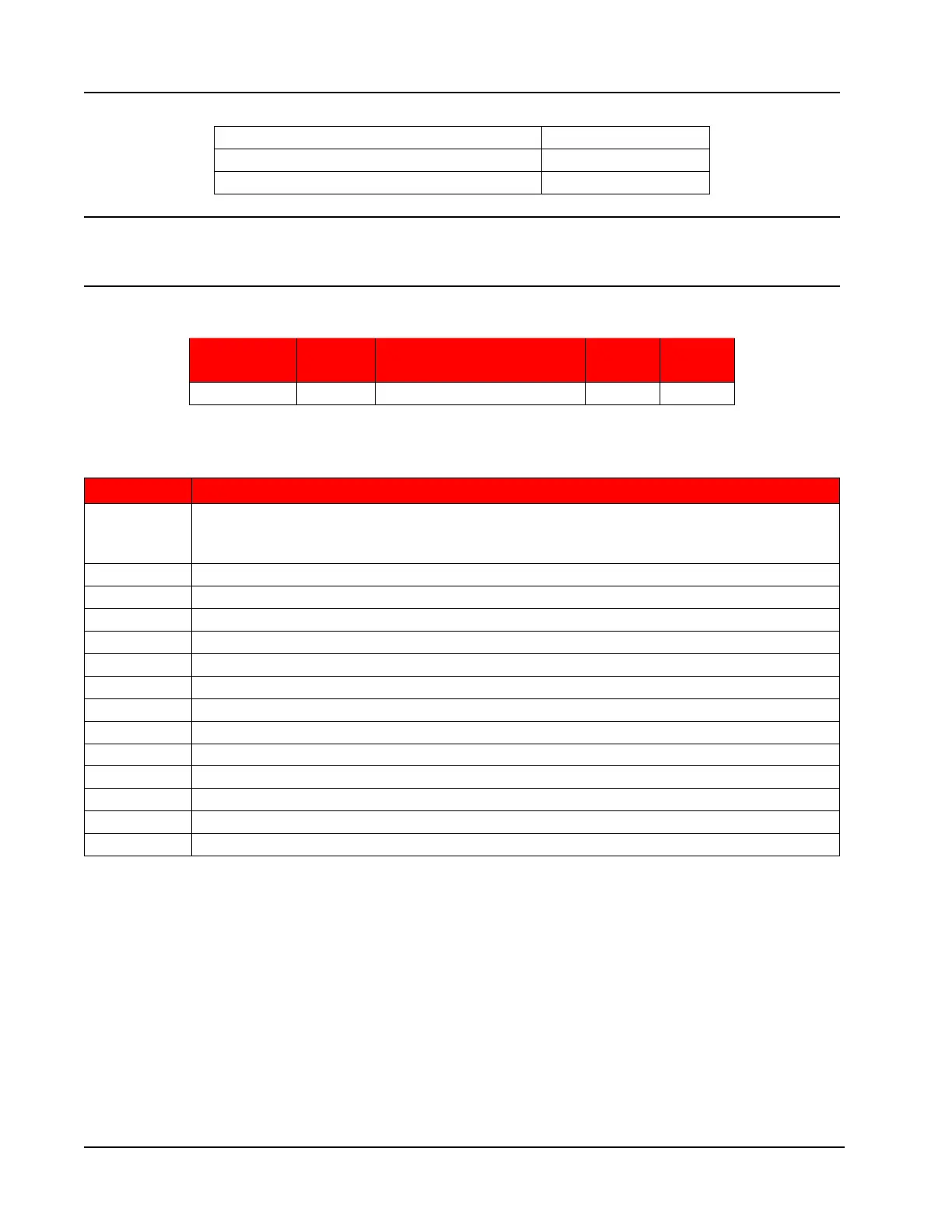
Control Registers
Register
(Decimal)
Register
(Hex) Description
Data
Type Access
70 46 Control Register 1 U16 R/W
The Control Registers allow specic functions to be implemented via the communications port. The
following table shows the value to be written to the control register to implement the desired function.
Code Function
20000 Transfers the polling totals and averages and polling run times to the previous polling totals,
averages and previous run-time registers, increments the polling index register, and resets
the polling totals, averages and polling run-time registers.
30000 Clears all ow totals
30001 Clears Flow Run 1 totals
30003 Clears Turbine 1 totals
30004 Clear Turbine 2 totals
30050 Clears all pulse output latches
30051 Clears a Pulse Output 1 latch
30061 Adds pulses specied in Control Register 2 to Pulse Output 1 Accumulator
30100 Clear all Alarm States
30101 Clear Flow Run Alarm Status
30102 Clear Input Alarm Status
40000 Loads factory defaults
40040 Resets the microcontroller (watchdog)
50050 Creates a partial archive record (daily and interval)