49
Scanner
®
2000 microEFM Section 2
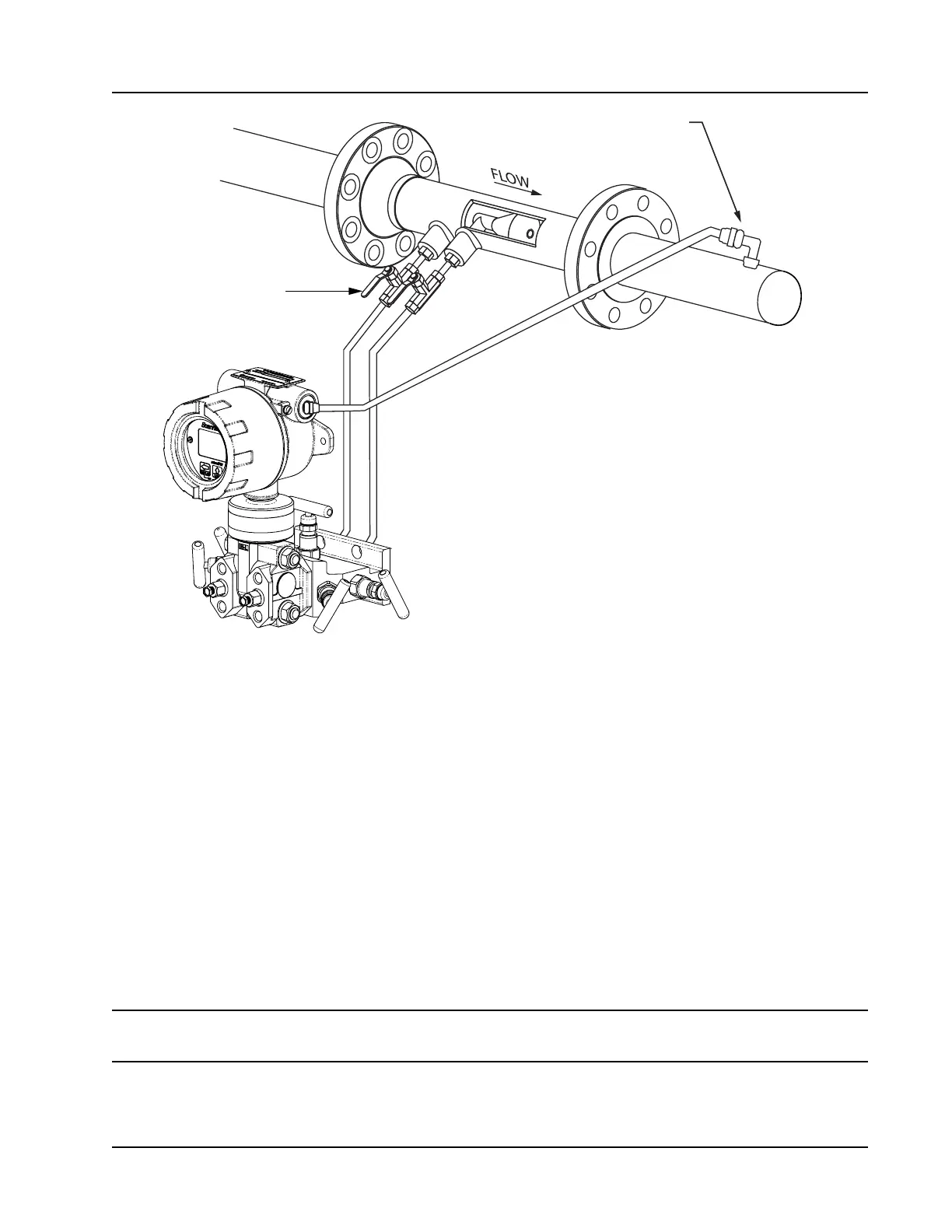
RTD assembly
Positioning of sensor below the
meter and slope of tubing helps
prevent gas bubbles from entering
the liquid
Shut-off valves
throttle flow to
the manifold
and MVT
Figure 2.11—Remote-mount liquid run installation (shown here with a cone meter). The remote-mount method
can be used with an orice meter as well.
1. Verify that the meter is properly installed in the ow line (per manufacturer’s instructions).
2. Mount the Scanner 2000 to a 2-in. pipe or to a at, vertical surface using bolts and the mounting holes in
the enclosure. A horizontal pipe is recommended, as additional hardware may be required for a vertical
pipe mount to provide clearance for the manifold block.
3. Install tubing and ttings to connect the high-pressure and low-pressure taps of the DP meter to the pro-
cess connections of the block manifold. Install a pair of shut-off valves near the high and low ports of the
DP meter. Use a suitable compound or tape on all threaded process connections.
4. Install the RTD assembly in the thermowell. Remove the plug from a conduit opening in the top of the
Scanner 2000 enclosure, route the RTD assembly cable through the conduit opening and connect it to the
main circuit board. A wiring diagram for the RTD assembly is provided in Figure 3.5, page 66. For hazard-
ous areas, review Hazardous Area Installations, page 27.
5. Route any additional inputs/outputs or COM connections, etc. through the conduit opening in the top of
the Scanner 2000. For hazardous areas, review Hazardous Area Installations, page 27.
Note To prevent ttings from turning and/or to avoid putting tension on stainless steel tubing, use a backup
wrench to attach stainless steel tubing to shut-off valves, or sensor ports.
6. To eliminate air bubbles in the MVT, manifold, and legs connecting them to the meter, ll the legs with
uid. Choose a uid that is safe for the environment, and stable when depressurized.