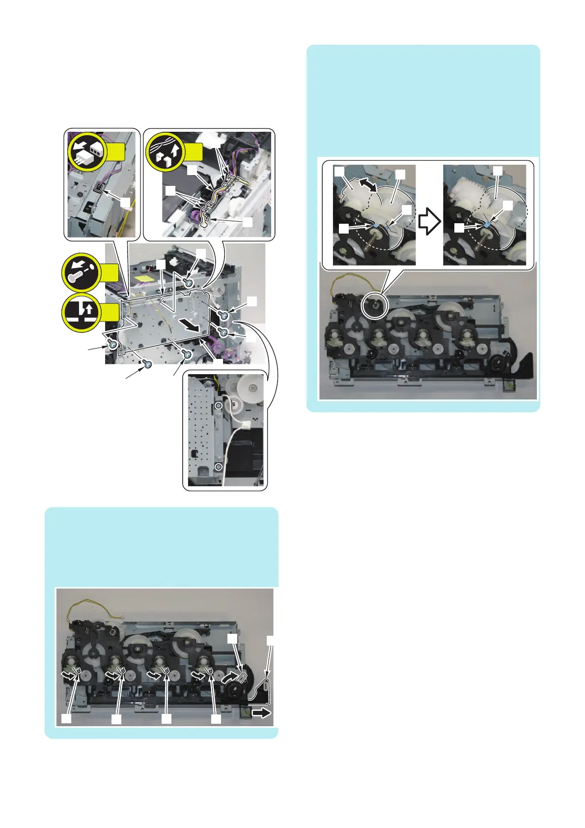
16. Remove the wire harness [1], and remove the Drive
Unit [2].
• 5 Fixing Guides [3]
• 1 Connector [4]
• 6 Screws [5]
• 1 Claw [6]
[2]
[5]
[6]
[5]
[5]
[5]
[5]
[5]
[4]
[3]
[3]
[3]
[1]
6x
5x
1x
1x
NOTE:
The Main Drive Unit side needs to be in the following
condition when installing the Main Drive Unit.
• 4 Arm Shafts [1] are on the right side.
• 1 Front Door Arm [2] is pulled out.
• 1 link [3] is on the right side.
NOTE:
The Main Drive Unit side needs to be in the following
condition when installing the Main Drive Unit.
• The directions of the groove [A] of the gear [1] of the
Main Drive Unit and the groove [B] of the Gear Cover
of the Main Drive Unit are aligned.
If the directions are not aligned, rotate the gear [2] to
align the directions of the groove [A] of the gear and
groove [B] of the Gear Cover.
4. Disassembly/Assembly
178
 Loading...