Appendix A APG & System Status Pin Assignment
A-1
Appendix A APG & System Status Pin
Assignment
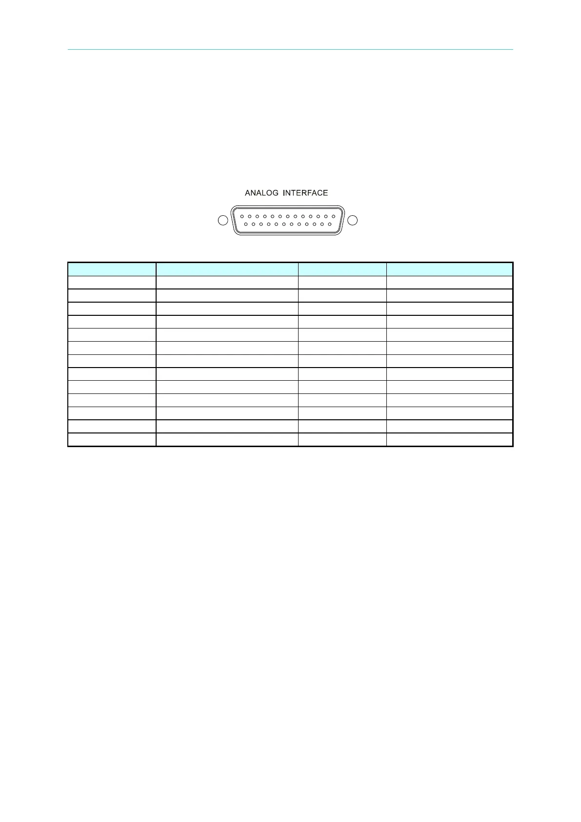
The 25-pin connector is located on the rear panel. The pin definitions are shown in Figure A-1:
Figure A-1
(1) PIN 1: +12V API auxiliary power for APG only (maximum output current: 10mA); see
section 3.3.1.1 for a detailed description.
(2) PIN 2: AVO_SET_R, voltage programming for APG only that allows users to set the
“resistance form”; see section 3.3.1.1 for a detailed description.
(3) PIN 3: AVO_SET_C, voltage programming for APG only that allows users to set the
“current form”; see section 3.3.1.1 for a detailed description.
(4) PIN 4: AVO_SET_V, voltage programming for APG only that allows users to set the
“voltage form”; see section 3.3.1.1 for a detailed description.
(5) PIN 5: AVO_MEAS_C, voltage programming for APG only that allows users to set the
“current form”; see section 3.3.1.1 for a detailed description.
(6) PIN 6: AVO_MEAS_V, voltage programming for APG only that allows users to set the
“voltage form”; see 3.3.1.1 for a detailed description.
(7) PIN 7: N.C.
(8) PIN 8: PROG_TRIG, the external trigger signal (positive edge trigger) in program editing
mode; see section 4.1.2.2 for a detailed description.
(9) PIN 9: _INHIBIT, this function uses Pin 9 of the ANALOG INTERFACE to turn off the
Power Supply when outputting; see section 3.3.5.4 for a detailed description
(10) PIN 10: DCOUT_ON, when the DC Power Supply output is ON and the voltage exceeds
VDC_R, Pin10 (DCOUT_ON) of SYSTEM STATUS on the rear panel will go HIGH.
When the DC Power Supply output voltage is lower than the VDC_F setting, Pin10
(DCOUT_ON) of SYSTEM STATUS on the rear panel will go LOW; see 3.3.2.5 for a
detailed description.
(11) PIN 11: CV_CC, this pin is HIGH when in CV mode and is LOW when in CC mode.