Programmable DC Power Supply (with Solar Array Simulation) 62000H Series
Operating & Programming Manual
4.2.1.2 Setting END_VOLTAGE
1. Use the “ ”, “ ” keys to move the cursor to the column to be set as shown in
Figure 4-19 (2). Set the end voltage of STEP MODE.
2. Use the numeric keys
-
or the “Rotary” ( ) knob to set the value.
3. Press “ ” to confirm.
4. Press “ ” to return to Figure 4-1.
4.2.1.3 Setting RUN_TIME
1. Use the “ ”, “ ” keys to move the cursor to the column to be set as shown in
Figure 4-19(3). Set the run time of STEP MODE. The time format is HOUR:MIN:SEC
and the maximum setting is 99 hours 59 minutes and 59.99 seconds.
2. Use the numeric keys
-
or the “Rotary” ( ) knob to set the value.
3. Press “ ” to confirm.
4. Press “ ” to return to Figure 4-1.
When V_STEP MODE ends the hardware output voltage will remain at
the END_VOLTAGE setting.
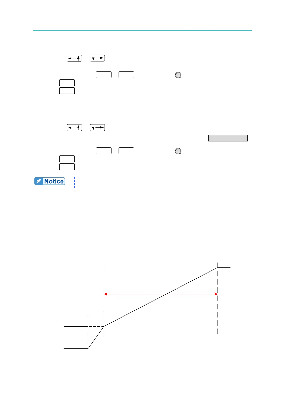
Ex. 1: Set the START_VOLTAGE to 10V, END_VOLTAGE to 50V and RUN_TIME to 10
minutes.
CASE1: The hardware initial voltage is 0V and the output waveform is shown in Figure
4-20.
CASE2: The hardware initial voltage is 10V and the output waveform is shown in
Figure 4-21.
CASE3: The hardware initial voltage is 20V and the output waveform is shown in
Figure 4-22.
Figure 4-20
START
10(MIN)
50V
0V
10V
1V/mS