Manual Operation
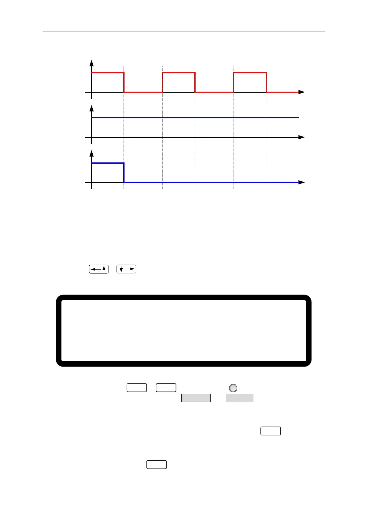
_INHIBIT
SIGNAL
INHIBIT
=DISABLE
INHIBIT
=ENABLE
Output
Output
Figure 3-77
3.3.5.5 SAFETY INT.LOCK
This function controls the power supply’s ON/OFF function directly through Pin 21
(INTERLOCK) of the ANALOG INTERFACE.
1. Use the “
” “ ” keys to move the cursor to the column to be set as shown in
Figure 3-78.
Figure 3-78
2. Use the numeric keys
-
or the “Rotary” ( ) knob to set the SAFETY
INT.LOCK mode. There are two options, DISABLE and ENABLE.
1. Selecting DISABLE: Disables this function.
2. Selecting ENABLE: Sets SAFETY INT.LOCK to ENABLE. The DC Power
Supply’s ON/OFF is still controlled by “
”. When PIN
21 of the ANALOG INTERFACE is at a low level, it indicates
the power supply is outputting normally and when it is at a
high level, it stops the power supply output temporary (the
“
” is still on) and issues a protection signal. Once Pin
[ P R O T E C T I O N ]
O V P
= 6 0 0 . 0 V
O C P
= 1 8 . 9 0 A
O P P
= 5 2 5 0 . 0 W
R E M O T E I N H I B I T
= D I S A B L E P U L L = H I G H
S A F E
T Y I N T . L O C K
= D I S A B L E _ P U L L = H I G H
E X T O N / O F F = D I S A B L E P U L L = H I G H
▼