Programmable DC Power Supply (with Solar Array Simulation) 62000H Series
Operating & Programming Manual
21 of the ANALOG INTERFACE is returned to a low level,
the DC Power Supply will continue to output normally.
3. Press “ ” to confirm.
4. Press “
” to return to the MAIN PAGE.
3. If a protection occurs due to a SAFETY INT.LOCK signal the MAIN PAGE will display the
protection message as shown in Figure 3-79.
V = 6 0. 0 0 V I = 1 0. 0 0 _ A O F F
0 . 0 0 0 0 V 0 . 0 0 0 0 A
S A F E T Y I N T E R L O C K 0 . 0 W
Figure 3-79
4. Pin 21 is a TTL Level input pin. The initial state can be set to PULL=HIGH or
PULL=LOW.
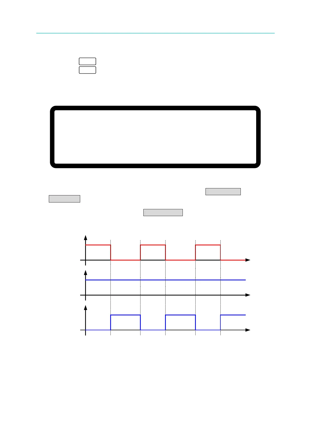
5. When the DC Power Supply is set to OUTPUT = ON, the SAFETY INT.LOCK signal will
control the output as shown in Figure 3-84.
INTERLOCK
SIGNAL
INTERLOCK
=DISABLE
INTERLOCK
=ENABLE
Output
Output
Figure 3-80