Manual Operation
1. Table 3-4 shows the power range of OPP.
Table 3-4
2. The OPP protection point is based on the comparison of the calculated
power of the output current and remote sense voltage.
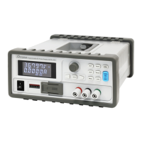
If an OPP occurs the MAIN PAGE will displaty a protection message as shown in Figure 3-74.
V
= 6 0
.
0 0 V I = 1 0. 0 0 _
A O F F
0 . 0 0 0 0 V 0 . 0 0 0 0 A
O P P 0 . 0 W
Figure 3-74
3.3.5.4 REMOTE INHIBIT
This function controls the power supply’s ON/OFF function directly through PIN 9 (_INHIBIT)
of the ANALOG INTERFACE in the APG & SYSTEM STATUS menus.
1. Use the “
” “ ” keys to move the cursor to the column to be set as shown in
Figure 3-75.
[ P R O T E C T I O N
]
O V P
= 6 0 0 .
0 V
O C P
= 1 8 . 9 0 A
O P P
= 5 2 5 0
. 0 W
R E M O T E I N H I B I T
= D I S A B L E _
P U L L = H I G H
S A F E
T Y I N T . L O C K
= D I S A B L E P U L L = H I G H
E X T O N /
O F F = D I S A B L E P U L L = H I G H
▼
Figure 3-75
2. Use the numeric keys
-
or the “Rotary” ( ) knob to set the REMOTE
INHIBIT mode. There are two options: DISABLE and ENABLE.
1. Selecting DISABLE: Disables the remote function.
 Loading...
