Programmable DC Power Supply (with Solar Array Simulation) 62000H Series
Operating & Programming Manual
Figure 3-46
5. The units are now ready to be used in the series/parallel mode.
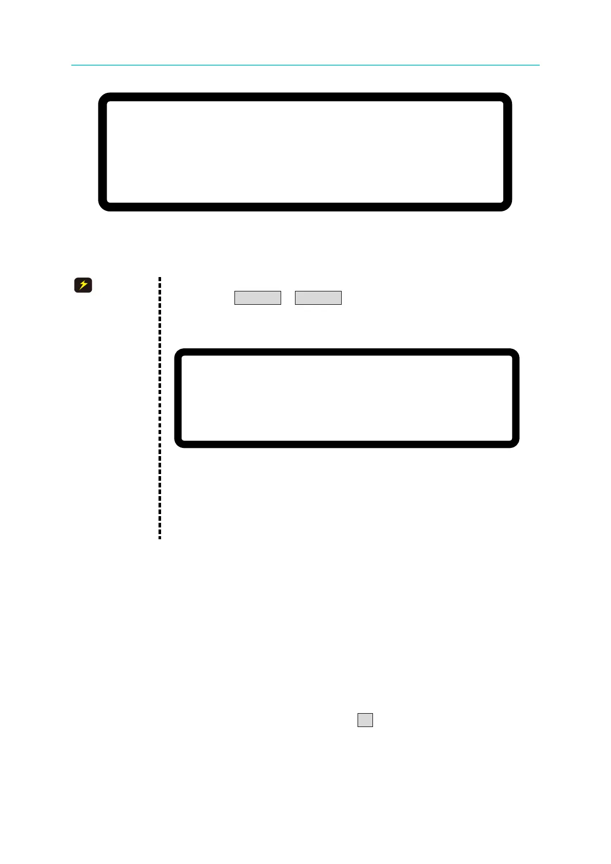
1. Communication errors will occur if the SLAVE settings are the same
(such as SLAVE 1 & SLAVE 1). The MAIN PAGE of the MASTER
unit will show the following message if this type of error occurs. First
exit the series/parallel operation and then change the SLAVE setting
to resume operation.
S L A V E 1
M E A S
.
E R R
Figure 3-47
2. Once the series/parallel settings are completed, the settings can be
saved. After all machines are powered off, turn on the SLAVEs first
and then the MASTER as it will automatically set the series/ parallel
3.3.3.4 Setting Series Parameters
The following parameter setting screens display once the software communication and
hardware settings for series operation are completed - (1) MAIN PAGE, (2) SYSTEM SETUP,
(3) OUTPUT SETUP and (4) PROTECTION.
3.3.3.4.1 Setting MAIN PAGE
MAIN PAGE is used to set voltage (V) and current (I). The difference between single unit
and series operation is that the voltage setting will increase according to the number of units
connected in series. The voltage setting is indicated by ΣV for easy identification. When
set to MASTER, MST will appear in the window’s upper right corner as shown in Figure 3-48
below.