Programmable DC Power Supply (with Solar Array Simulation) 62000H Series
Operating & Programming Manual
14
Use the “ ” and “ ” keys to move the cursor to the
parameter to be modified.
15
Voltage Rotary Knob:
Turn the knob “ ” to input data or select an item.
16
Current Rotary Knob:
Turn the knob “ ” to input data or select an item.
17
Switches the power “ON” or “OFF”.
18
Use the left (right) bracket to attach the Power Supply to
the Rack.
19
When the slave model is “ON”, the LEDs show its status.
The green light indicates POWER ON, the yellow light
indicates the data is transmitting or communication is
normal, the red light indicates a fault occurred during
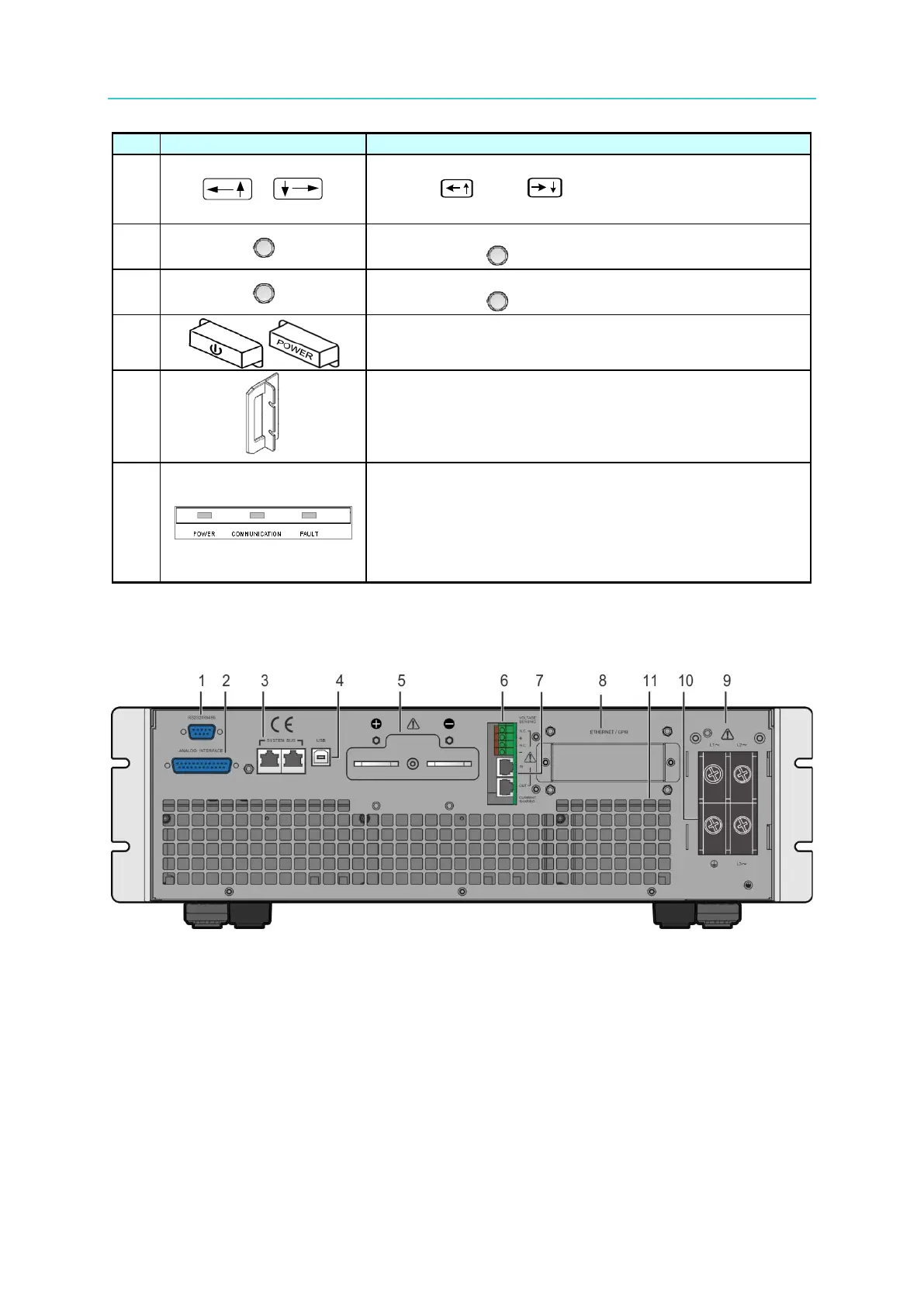
1.4.2 Rear Panel
Figure 1-6 Rear Panel of 62000H with Solar Array Simulation