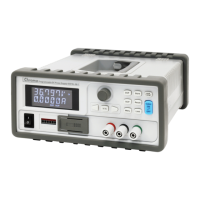
Programmable DC Power Supply (with Solar Array Simulation) 62000H Series
Operating & Programming Manual
Table of Contents
1. Overview ........................................................................................................... 1-1
1.1 Introduction ......................................................................................................... 1-1
1.2 System Functions ............................................................................................... 1-1
1.2.1 Operating Modes ......................................................................................... 1-1
1.2.2 Protection .................................................................................................... 1-1
1.2.3 Output/Indication ......................................................................................... 1-2
1.2.4 Input Control Signals ................................................................................... 1-2
1.2.5 Measuring & Editing .................................................................................... 1-2
1.3 Specifications ...................................................................................................... 1-2
1.3.1 Other Specifications .................................................................................... 1-4
1.4 Function Keys ................................................................................................... 1-10
1.4.1 Front Panel ............................................................................................... 1-10
1.4.2 Rear Panel ................................................................................................ 1-12
2. Installation ........................................................................................................ 2-1
2.1 Checking the Package ........................................................................................ 2-1
2.1.1 Maintenance & Cleaning ............................................................................. 2-2
2.2 Preparation for Use ............................................................................................. 2-2
2.2.1 Normal Environment Conditions .................................................................. 2-3
2.3 Input Power Requirements .................................................................................. 2-3
2.3.1 Ratings ........................................................................................................ 2-3
2.3.2 Input Connections ....................................................................................... 2-3
2.4 Remote Sensing ................................................................................................. 2-5
2.4.1 Correct Connection ..................................................................................... 2-5
2.4.2 Reverse Connection of Remote Sensing Wire Polarity ................................ 2-7
2.5 Output Connection .............................................................................................. 2-7
2.5.1 Rear Panel Output....................................................................................... 2-7
2.5.2 Connecting Wire Specifications ................................................................... 2-9
2.5.3 Parallel Capacitance Specifications ........................................................... 2-10
2.5.4 Installing the Handle (62150H for example) ............................................... 2-10
2.6 Power-On Procedure ........................................................................................ 2-11
3. Manual Operation ............................................................................................. 3-1
3.1 Introduction ......................................................................................................... 3-1
3.2 Setting Voltage & Current ................................................................................... 3-1
3.3 Setting Configuration .......................................................................................... 3-2
3.3.1 SYSTEM SETUP ........................................................................................ 3-5
3.3.1.1 APG ........................................................................................................ 3-5
3.3.1.2 BUZZER ................................................................................................ 3-10
3.3.1.3 POWER ON STATUS ........................................................................... 3-10
3.3.2 OUTPUT SETUP ...................................................................................... 3-12
3.3.2.1 VOLTAGE LIMIT SETTING ................................................................... 3-13
3.3.2.2 CURRENT LIMIT SETTING .................................................................. 3-14
3.3.2.3 VOLTAGE SLEW RATE ........................................................................ 3-15
3.3.2.4 CURRENT SLEW RATE SETTING ....................................................... 3-16
3.3.2.5 Setting DC_ON ...................................................................................... 3-17
3.3.2.6 Setting IV CURVE Parameters .............................................................. 3-18
3.3.3 SERIES/PARALLEL .................................................................................. 3-21
3.3.3.1 Connecting Series/Parallel Output Cables ............................................. 3-22
3.3.3.2 Assembling Series/Parallel Communication Interface ............................ 3-22
3.3.3.3 Setting Series/Parallel Operation Mode ................................................. 3-25
3.3.3.4 Setting Series Parameters ..................................................................... 3-30
 Loading...
