Programmable DC Power Supply (with Solar Array Simulation) 62000H Series
Operating & Programming Manual
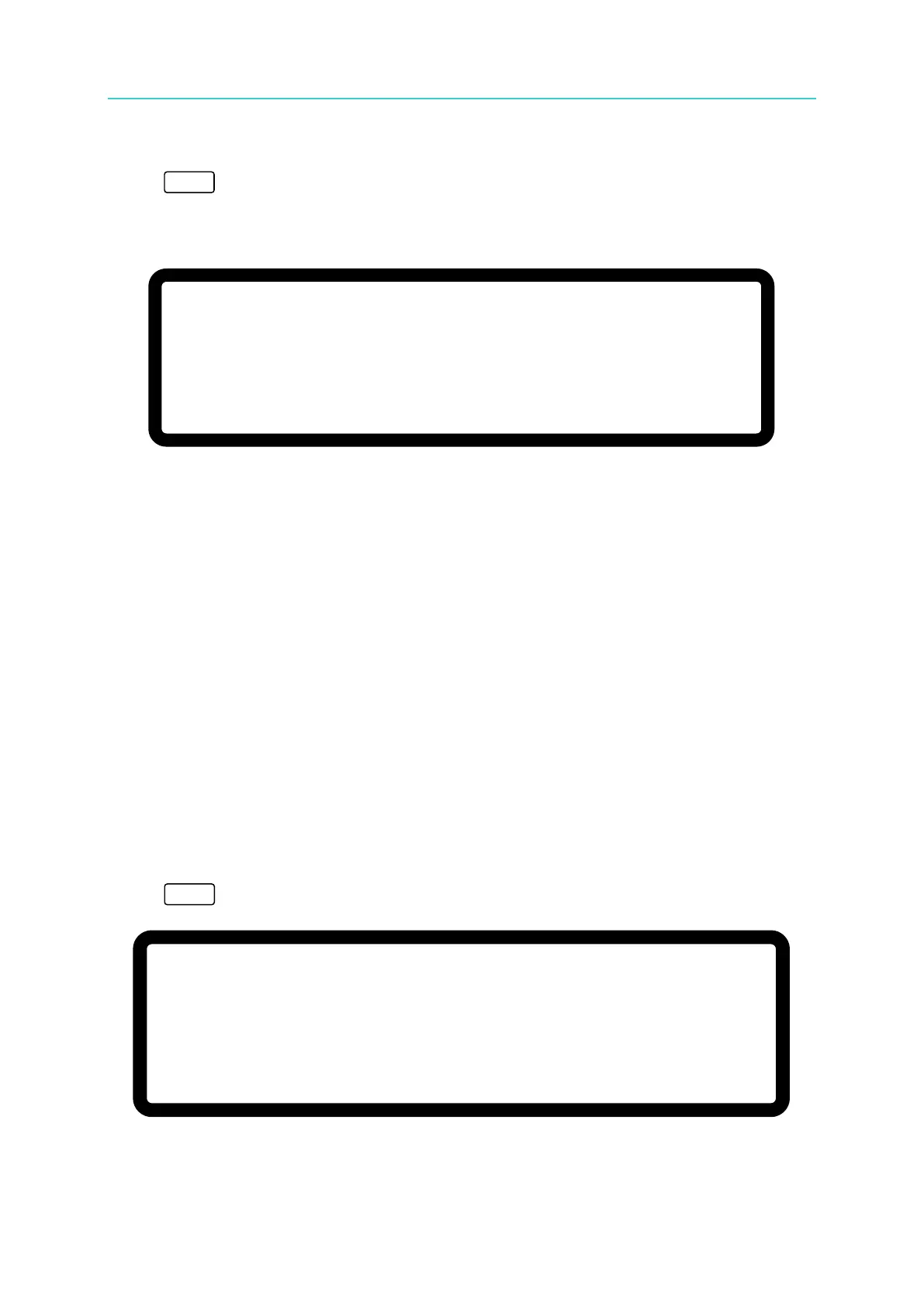
To set the current (CC MODE):
Press “
”. The remaining steps are the same as the voltage settings, as shown in Figure
3-2. (To keep the output in CC mode the voltage setting must be larger than the load voltage;
otherwise, the output current will not be equal to the set current.)
V
= 0
.
0 0 V I
= 0
.
0 0
_
A O F F
0 . 0 0 0 0 V 0 . 0 0 0 0 A
0 . 0 W
Figure 3-2
3.3 Setting Configuration
The configuration setting function allows users to set the system functions for the DC Power
Supply. The system functions that can be set during configuration are:
Sets various system parameters including GPIB address.
Sets various output parameters including voltage/current slew rate etc.
Sets the parameters for series or parallel mode.
Sets the parameter arrangement on panel.
Sets the parameters for each protection function.
Sets the production information and settings.
Calibrates the DC Power Supply.
Sets the system parameters for GPIB address etc.
Selects CV/CC mode or the output mode with IV function.
To set the configuration:
Press “
” to enter into the config setting screen as shown in Figure 3-3.
Figure 3-3
C H O I C E = S Y S T E M S E T U P [ C O N F I G ]
1. S Y S T E M S E T U P 5. P R O T E C T I O N
2. O U T P U T S E T U P 6. F A C T O R Y S E T T I N G
3. S E R I E S / P A R A L L E L 7. C A L I B R A T I O N
4. D I S P L A Y 8. R E M O T E S E T U P
9. O U T P U T M O D E