Programmable DC Power Supply (with Solar Array Simulation) 62000H Series
Operating & Programming Manual
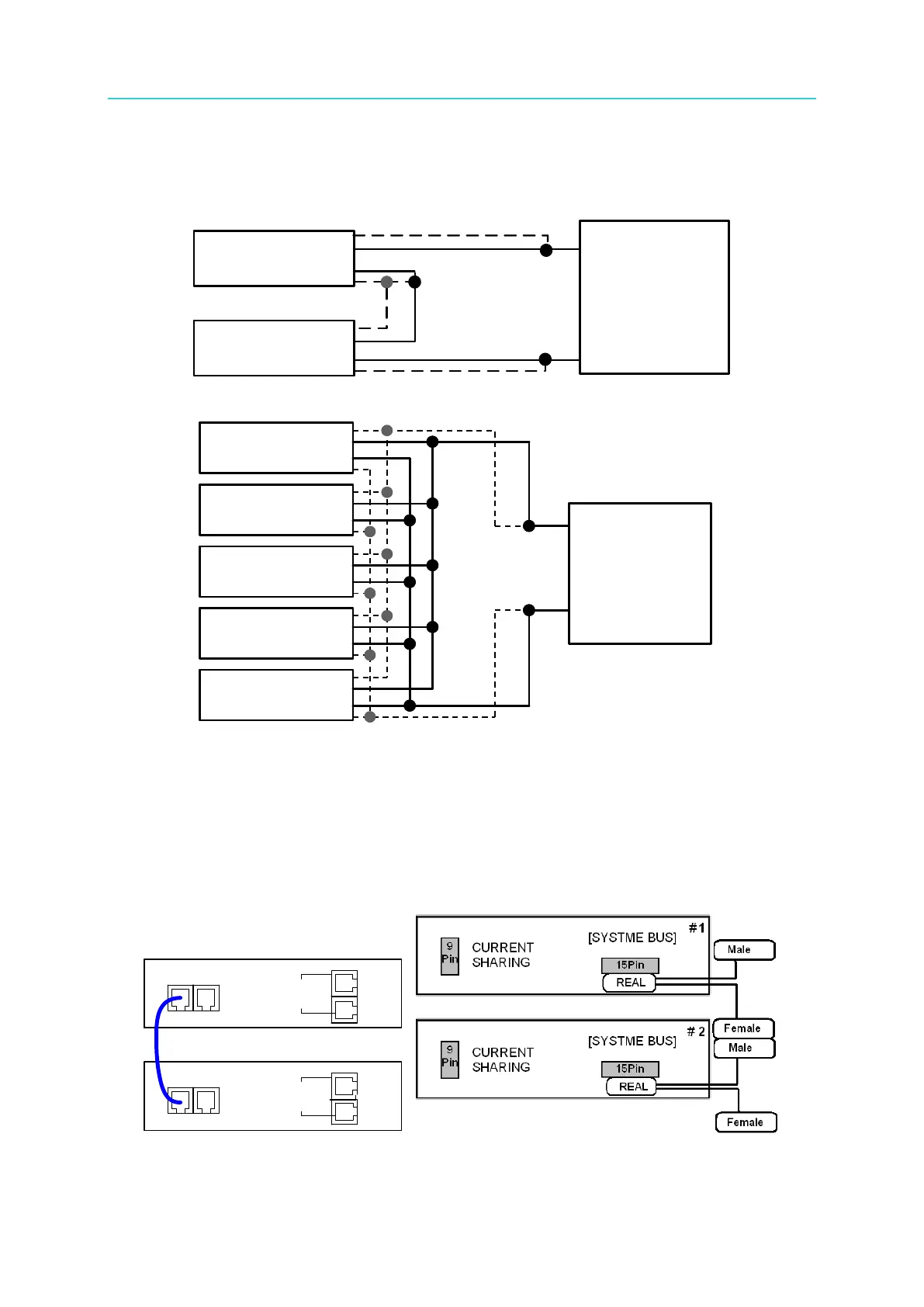
3.3.3.1 Connecting Series/Parallel Output Cables
Figure 3-32 and Figure 3-33 show how to connect the serial and parallel output cables.
Figure 3-32
Figure 3-33
3.3.3.2 Assembling Series/Parallel Communication Interface
1. When the DC Power Supplies are connected in series, the SYSTEM BUS connectors on
the rear panel must be connected as shown in Figure 3-34(a.). For the 62020H-150S,
connect the cables as shown in Figure 3-34(b).
CURRENT
SHARING
CURRENT
SHARING
1 #
2 #
[ SYSTEM BUS]
[ SYSTEM BUS]
(a) (b)
Figure 3-34
SVO+
VO+
VO
SVO
SVO+
VO+
VO-
SVO
DUT
SVO+
VO+
VO
SVO
SVO+
VO+
VO -
SVO
DUT
62150H-600S
62150H-600S
--
--
--
+
-
SVO+
VO+
VO-
SVO-
SVO+
VO+
VO-
SVO-
SVO+
VO+
VO-
SVO-
SVO+
VO+
VO-
SVO-
SVO+
VO+
VO-
SVO-
DUT
SVO+
VO+
VO-
SVO-
SVO+
VO+
VO-
SVO-
SVO+
VO+
VO-
SVO-
SVO+
VO+
VO-
SVO-
SVO+
VO+
VO-
SVO-
DUT
62150H-600S
62150H-600S
62150H-600S
62150H-600S
62150H-600S
+
-