Manual Operation
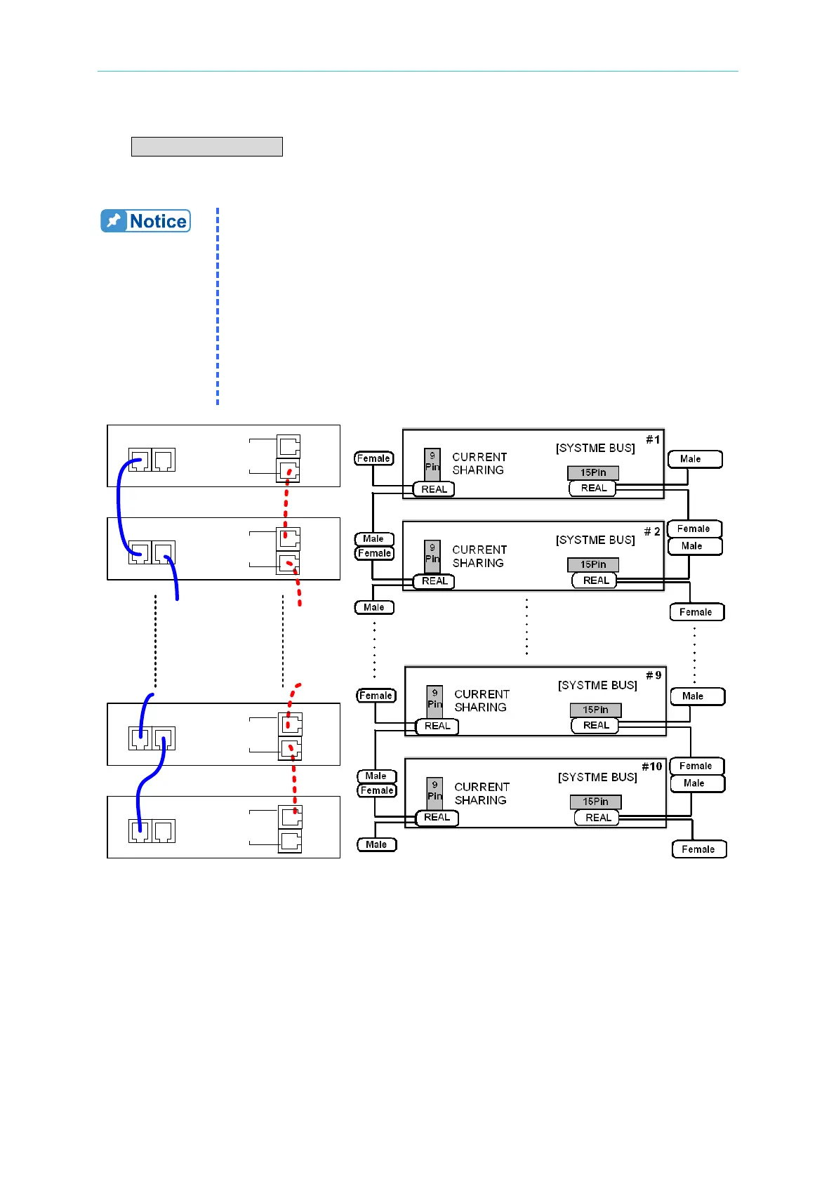
2. When the DC Power Supplies are connected in parallel, both the SYSTEM BUS and
CURRENT SHARING connectors must be connected as shown in Figure 3-35 (a) [and
Figure 3-35 (b) for the 62020H-150S]. For the A620028 and A620027 the MASTER unit
and ANALOG must be connected as shown in Figure 3-36.
1. The A620028 and A620027 SLAVE models only work when the
MASTER firmware version is 1.30 or above. If a firmware upgrade is
required, contact Chroma.
2. The A620028 and A620027 SLAVE models have a 1 to 2 ANALOG
communication cable labeled “SLAVE”. This standard accessory is
for A620028 and A620027 use only. The other 1 to 2 ANALOG cable
labeled “MASTER” connects the MASTER side with the A620028
and A620027 as shown in Figure 3-36 (this cable is optional).
3. Plug in the 62020H-150S SYSTME BUS CABLE connector labeled
“REAL” to the device rear panel. See Figure 3-35
(b) for connecting
other devices for communication.
CURRENT
SHARING
CURRENT
SHARING
CURRENT
SHARING
CURRENT
SHARING
1 #
2 #
10 #
9#
[ SYSTEM BUS]
[ SYSTEM BUS]
[ SYSTEM BUS]
[ SYSTEM BUS]
(a) (b)
Figure 3-35