Programmable DC Power Supply (with Solar Array Simulation) 62000H Series
Operating & Programming Manual
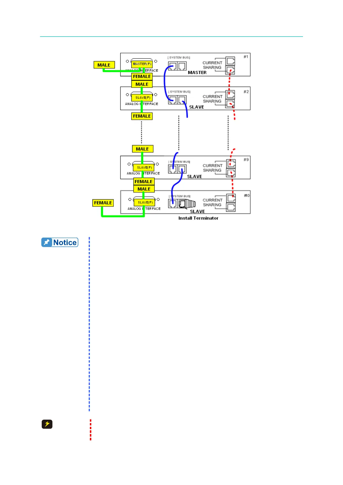
Figure 3-36
1. Each DC Power Supply has two RS485 female interface connectors.
They must be connected for series or parallel operation. There is
no difference between left and right; just connect one after another
as shown by the solid line in
Figure 3-34 or Figure 3-35. For the
62020H-150S, connect the 15P 1 to 2 cable labeled “REAL” to the
rear panel; also connect the two cables as shown in Figure 3-34 or
Figure 3-35. The maximum length for the communication cable is 7.2
meters. Exceeding the length limit may result in unstable
operation.
2. Each DC Power Supply has two CURRENT SHARING connecting
terminals. Connect the output terminal of the first Power Supply to
the input terminal of the second Power Supply and so forth as shown
by the dotted lines in Figure 3-35. For the 62020H-150S, connect the
9P 1 to 2 cable labeled “REAL” to the rear panel; also connect the
two cables as shown in Figure 3-35. Be sure to use the CURRENT
SHARING communication cable provided by CHROMA. The
maximum length for the CURRENT SHARING cable is 3.4 meters.
Exceeding the length limit may result in unstable operation.
3. The CURRENT SHARING communication cable must be securely
connected during parallel operation or it may result in unstable
operation.
4. When the A620028 and A620027 are connected to the MASTER
unit, install a Terminator on the last SYSTEM BUS of the parallel
path as shown in Figure 3-36.
1. The DC Power Supply could malfunction or be damaged if the
CURRENT SHARING cable is connected incorrectly when in parallel