Installation
5. Connect the black or brown metal wire of the 62020H-150S to the “L”
terminal.
1. To protect the operator, the wire connected to the GND terminal
( ) must be connected to the earth. This DC Power Supply must
be operated with an adequate ground connection.
2. Installation of the power cord must be done by a professional and
compliant with local electrical codes.
1. Be sure to select an appropriate withstand voltage cable based on
the desired input voltage.
2. To ensure operational safety, select a proper current rated
BREAKER for the input power source that switches each phase and
connect it to the input terminal.
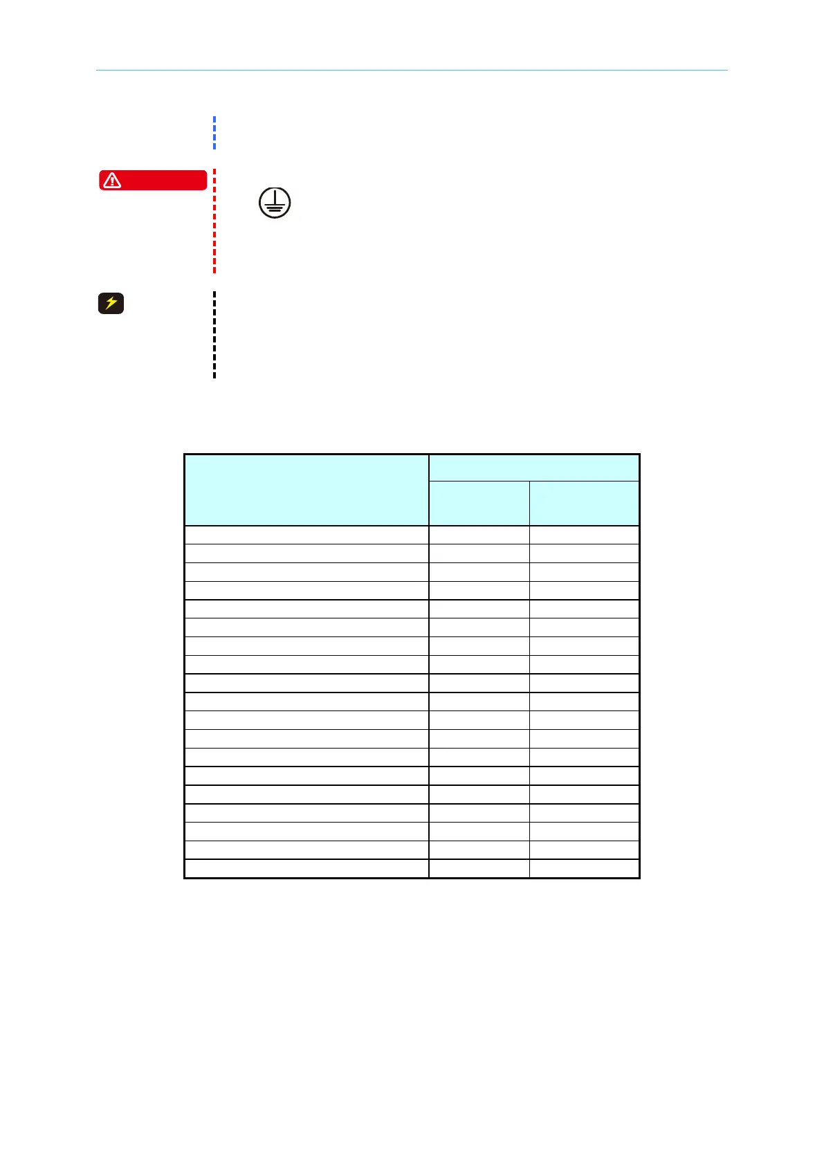
Table 2-1 is a cable specification for PVC (105°C) with the ambient temperature at 30°C.
Table 2-1 PVC (105°C) Cable Specification
Conductor Area
Sectional Area mm
2
Copper
Lead
2.4 Remote Sensing
2.4.1 Correct Connection
1. Connect the remote sensing wire to ensure the output voltage equals the set voltage.
The DC Power Supply is able to compensate up to a 4% F.S. line voltage drop.
2. Figure 2-6 shows the correct connection. Use two wires to connect the positive and
negative connectors of the load to the remote sensing connector on the rear panel. The