Programmable DC Power Supply (with Solar Array Simulation) 62000H Series
Operating & Programming Manual
Figure 3-133
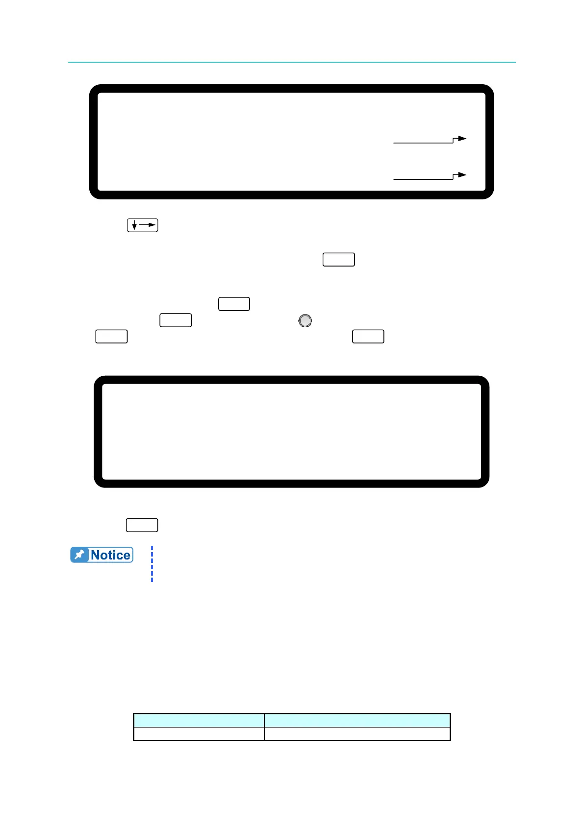
7. Press “
” again and the system will set the output voltage of Pin 19 on the rear
panel to 8.0V and the cursor stops at position [4] as shown in Figure 3-133. Input the
voltage read by DVM2 to position [4] and press “ ” to confirm.
8. The APG current calibration is done once the above actions are completed. To save the
calibration data, pressing “ ” will display a confirmation page as shown in Figure
3-134. Press “ ” or turn the “Rotary” ( ) knob to set SAVE=YES and press
“ ” to save it. If there is no need to save it, press “
” to return to the Calibration
screen.
[ S A V E A R G U M E N T ]
S A V E =
N O
Figure 3-134
9. Press “
” to return to the MAIN PAGE.
The calibration points may be different for other models (non
62150H-600S); perform the calibration following the instructions
3.3.7.6 IV Voltage Output & Measurement Calibration (62020H-150S
Only)
3.3.7.6.1 Hardware Requirements
The hardware required for calibration is shown in Table 3-11.
Table 3-11
Suggest Model or Capacity
HP 34401A or equivalent DVM
[ A P G C U R R E N T C A L I B R A T I O N
]
( M E A . ) O U T P U T V O L T A G E F O R M E A S U R E = 0 . 5 V
A C T U A L
A P G O U T P U T V O L T A G E = 0 . 0 0 0 _ V
( M E A . ) O U T P U T V O L T A G E F O R M E A S U R E = 8 . 0 V
A C T U A L A P G O U T P U T V O L T A G E = 0 . 0 0 0 V
[
3
]
[ 4 ]