Manual Operation
3.3.7.6.2 Setup
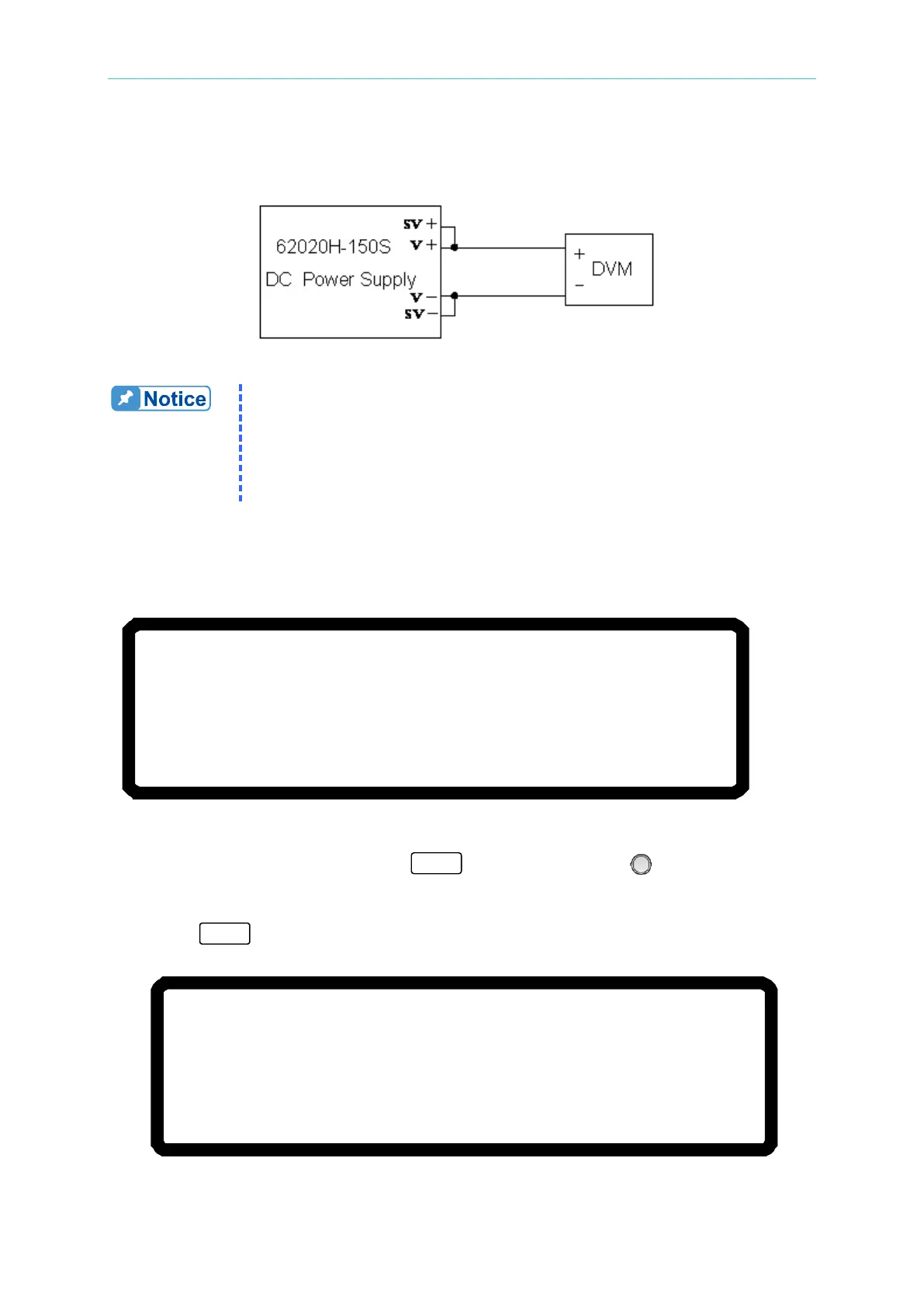
The wiring diagram is shown in Figure 3-135.
Figure 3-135
1. Before perfoming a calibration, ensure the resolution of the test
equipment exceeds the 62020H-150S specifications.
2. Set the Resolution of the HP34401 to SLOW 6 digit.
3. Key in at least 5 digits for each calibration point to ensure the Power
Supply accuracy after calibration.
4. This calibration function is only valid for the 62020H-150S.
3.3.7.6.3 Calibration Procedure
1. Go to the CALIBRATION the screen as shown in Figure 3-136.
[C A L I B R A T I O N]
CHOICE = VOLTAGE [P/M]
1.VOLTAGE [PROG. /MEAS. ]
2.CURRENT [MEAS. ]
3.CURRENT [PROG.]
4.APG VOLTAGE [PROG. /MEAS.]
5.APG CURRENT [PROG. /MEAS. ]
6.IV VOLTAGE[MEAS.] 7.IV CURRENT[MEAS. ]
Figure 3-136
2. In the CALIBRATION page, press “ ” or turn the “Rotary” ( ) knob to set
CHOICE=1.
3. Press “ ” to display the current calibration options as shown in Figure 3-137.
[V O L T A G E C A L I B R A T I O N ]
R E M O V E E X T E R N A L L O A D A N D P R E S S [
E N T E R ] _
S E T T I N G O U T P U T V O L T A G E
1 0 . 0 0 V
A C T U A L O U T P U T V O L T A G E = 0 . 0 0 0 0
V
S E T T I N G O U T P U T V O L T A G E
2 9
. 0 0 V
A C T U A L O U T P U T V O L T A G E = 0 . 0 0 0 0
V
Figure 3-137