Programmable DC Power Supply (with Solar Array Simulation) 62000H Series
Operating & Programming Manual
4. Verify the external load has been removed and press “ ” to confirm.
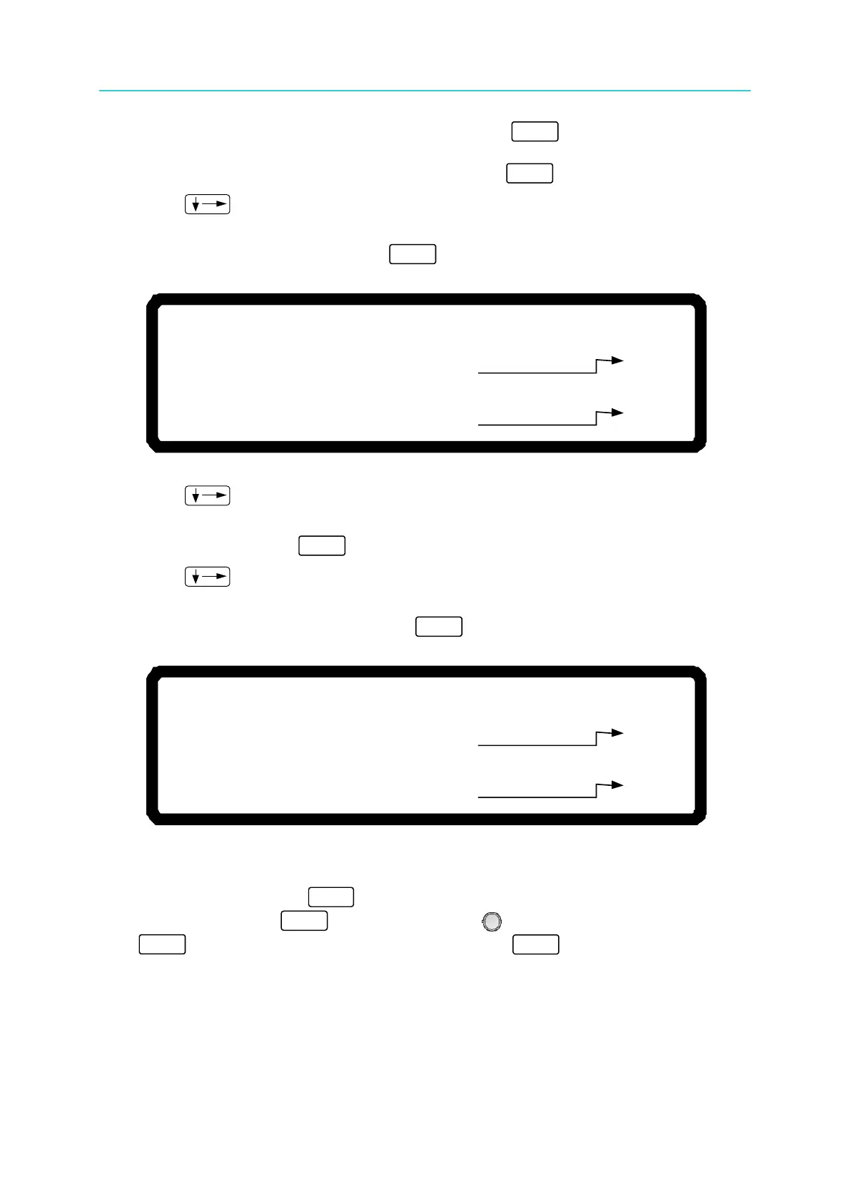
5. The device will output 10.00V and the cursor will stop at position [1] as shown in Figure
3-138. Enter the voltage read by the DVM and press “ ” to confirm it.
6. Press “ ” to do the second low voltage range point calibration. The device will
output 29.00V and the cursor will stop at position [2] as shown in Figure 3-138. Enter the
voltage read by the DVM and press “ ” to confirm it.
[V O L T A G E C A L I B R A T I O N]
R E M O V E E X T E R N A L L O A D A N D P R E S S[ E N T E R ]
S E T T I N G O U T P U T V O L T A G E 1 0 . 0 0 V
A C T U A L O U T P U T V O L T A G E= 9 . 9 9 9 8 _ V
S E T T I N G O U T P U T V O L T A G E
2 9 . 0 0
V
A C T U A L O U T P U T V O L T A G E=
2 8 .
V
[ 1 ]
[2 ]
9 9 8 2
Figure 3-138
7. Press “
” to do the high voltage range calibration. The device will output 38.00V
and the cursor will stop at position [3] as shown in Figure 3-139. Enter the voltage read
by the DVM and press “ ” to confirm it.
8. Press “ ” to do the second high voltage range point calibration. The device will
output 132.00V and the cursor will stop at position [4] as shown in Figure 3-139. Enter
the voltage read by the DVM and press “ ” to confirm it.
[
V O L T A G E C A L I B R A T I O N
]
R E M O V E E X T E R N A L L O A D A N D P R E S S
[ E N T E R ]
S E T T I N G O U T P U T V O L T A G E 3 8 . 0 0
V
A C T U A L O U T P U T V O L T A G E=
3 7 . 9 9 8 3
V
S E T T I N G O U T P U T V O L T A G E 1 3 2 .
0 0
V
A C T U A L O U T P U T V O L T A G E= 1 3 1 .
V
[
3 ]
[4 ]
9 9 9 1
Figure 3-139
9. The voltage calibration is done when the above actions are completed. To save the
calibrated values, press “ ” and a confirmation screen will appear as shown in
Figure 3-140. Press “ ” or turn the “Rotary” (
) knob to set SAVE=YES and press
“ ” to save it. If there is no need to save it, press “
” to return to the Calibration
screen.