Programmable DC Power Supply (with Solar Array Simulation) 62000H Series
Operating & Programming Manual
S T E P S T A T U S = A U T O E L A P S E
T I M E =
0
: 0
:
5 0
S T A R T _ V O L T
= 1 0 . 0 0 E N D
_ V O L T = 2 0 . 0 0
0
. 0 0 0 0 V 0 . 0 0 0 0
A
0 . 0 W
Figure 4-23
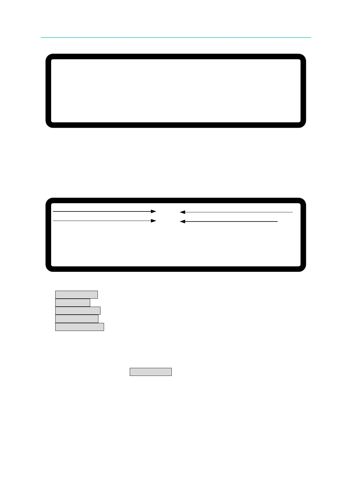
4.2.2.2 Description of Program V_Step Mode
Figure 4-24 shows the main execution page of V_STEP MODE. Items (1) - (4) in the figure
are explained below.
S T E P S T A T U S =
A U T O E L A P S E
T I M E = 0 : 0 : 5 0
S T A R T _ V O L T
= 1 0 . 0 0 E N D _ V O L T = 2 0 . 0 0
0
. 0 0 0 0 V 0 . 0 0 0 0 A
0 . 0 W
(3) (4)
(1) (2)
Figure 4-24
(1) START_VOLT: the start voltage setting of V_STEP MODE.
(2) END_VOLT: the end voltage setting of V_STEP MODE.
(3) STEP STATUS: the executing status of V_STEP MODE.
(4) ELAPSE TIME: the elapsed time of V_STEP MODE. The time format is
HOUR:MIN:SEC (the maximum display is 99 hours 59 minutes and 59 seconds).
4.3 IV PROGRAM
The IV Curve can be edited in IV PROGRAM. An IV-Program can add a maximum of 100 IV
curves to the IV-Sequence. Setting the IV-Sequence is described in 4.3.2. Figure 4-25 shows
the complete IV-Program structure.