Manual Operation
Key in at least 5 digits for each calibration point to ensure the Power
Supply accuracy after calibration.
3.3.7.5.3 Calibration Procedure (Example: Model 62150H-600S)
1. In the CALIBRATION page, press “ ” or turn the “Rotary” ( ) knob to set CHOICE
= 5.
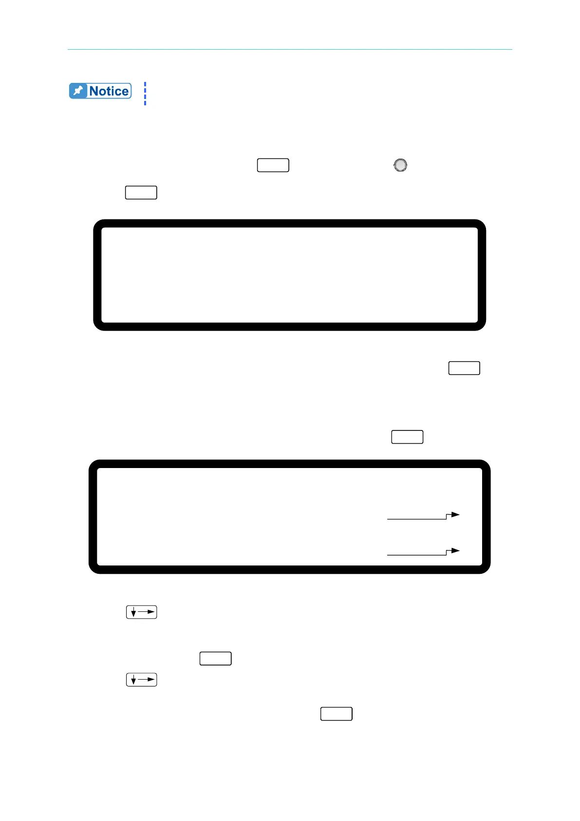
2. Press “ ” to display the current calibration options as shown in Figure 3-131.
[ A P G
C U R R E N T C A L I B R A T I O N ]
C H E C K A P G C O N N E C T I O N A N D P R E S S
[ E N T E R
]
_
( S E T ) I N P U T V O L T A G E F O R S E T T I N G
= 0
. 5
V
A C T U A L
A P G I N P U T V O L T A G E =
0 .
0 0 0
V
( S E T ) I N P U T V O L T A G E F O R S E T T I N G
= 8
. 0 V
A C T U A L
A P G I N P U T V O L T A G E =
0
. 0 0 0
V
Figure 3-131
3. Insure the interface connection on the rear panel is correct and then press “ ” to
confirm.
4. Input a 0.5V voltage signal on Pin 17. The cursor stops at position [1] as shown in Figure
3-132. Adjust the Power Supply to 0.5V±0.2V and use DVM1 to measure the reading of
the Power Supply. Input the voltage read by DVM 1 and press “ ” to confirm.
Figure 3-132
5. Press “
” again and input an 8.0V voltage signal on Pin 17. The cursor stops at
position [2] as shown in Figure 3-132. Adjust the Power Supply to 8V±0.2V and use
DVM1 to measure the reading of the Power Supply. Input the voltage read by DVM1 to
position [2] and press “ ” to confirm.
6. Press “ ” again and the system will set the output voltage of Pin 19 on the rear
panel to 0.5V and the cursor stops at position [3] as shown in Figure 3-133. Input the
voltage read by DVM2 to position [3] and press “ ” to confirm.
[ A P G
C U R R E N T C A L I B R A T I O N ]
C H E C K A P G C O N N E C T I O N A N D P R E S S [ E N T E R ]
( S E T
) I N P U T V O L T A G E F O R S E T T I N G = 0 . 5 V
A C T U A L A P G I N P U T V O L T A G E = 0 . 0 0 0 _ V
( S E T ) I N P U T V O L T A G E F O R S E T T I N G = 8 . 0 V
A C T U A L A P G I N P U T V O L T A G E =
0 . 0 0 0 V
[ 1 ]
[ 2 ]
 Loading...


