Overview
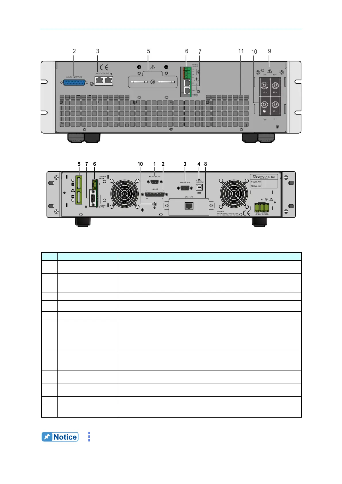
Figure 1-7 Rear Panel of Slave Model A620027/A620028
Figure 1-8 Rear Panel of 62020H-150S with Solar Array Simulation
Table 1-6 Description of Rear Panel
9-pin D type male connector. The control commands are transmitted
between power supply and PC for remote control.
Signal Connecting
25 pin signals that include APG input/output terminals and system status
signal terminals. See Appendix A for detailed pin assignments.
Bus for serial/parallel data transmission.
The USB bus is connected to the PC via this connector for remote control.
Output terminals of the DC Power Supply.
Connector
Connect this connector to the load to compensate for the voltage drop
generated due to cable resistance.
Connect the remote sense connector “+”
to the positive output terminal and the “–” connector to the negative output
terminal. Do NOT reverse the remote sense connectors to the “+”, “–”
Connector
When used in parallel mode, this cable must be connected to share the
output current. The cable must be removed when used in series mode or
standalone mode to prevent damage to the unit.
GPIB/ETHERNET
Connector (Option)
The GPIB/ETHERNET bus is connected to the PC via this connector for
remote control.
Inputs AC power from the power line and connects to the input stage
through this connector.
Earth Ground connection point.
Protects the fan. Do not block the fan mask to avoid accumulating heat
inside the machine.
The callout 8 in Figure 1-6 is the cover plate for the standard