Program Sequence
[ P R O G R A M
/
S T E P]
S T A R T
_
V O L T A G E = 0 . 0 0 V
E N D
_ V O L T A G E
= 0 . 0 0 V
R U N _ T I M E
=
0 :
0 : 0 . 0 0
▼
Figure 4-18
4.2.1 Setting V_STEP MODE
V_STEP MODE has 3 settings: (1) START_VOLTAGE, (2) END_VOLTAGE and (3)
RUN_TIME.
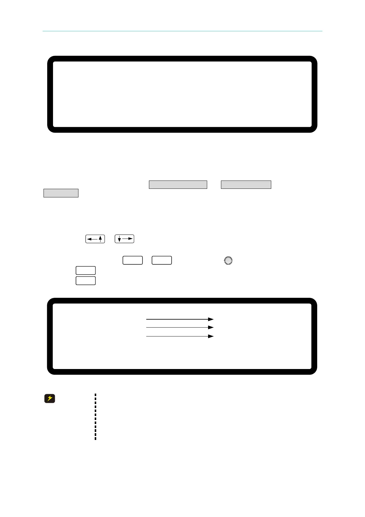
4.2.1.1 Setting START_VOLTAGE
1. Use the “ ”, “ ” keys to move the cursor to the column to be set as shown in
Figure 4-19 (1). Set the start voltage of STEP MODE.
2. Use the numeric keys
-
or the “Rotary” ( ) knob to set the value.
3. Press “ ” to confirm.
4. Press “ ” to return to Figure 4-1.
[ P R O G R A M / S T E P]
S T A R T _ V O L T A G E = 0 . 0 0 _ V
E N D _ V O L T A G E
= 0 . 0 0 V
R U N _ T I M E
= 0 : 0 : 0 . 0 0
▼
( 1 )
( 2 )
( 3 )
Figure 4-19
The initial voltage of the hardware may not be equal to the
START_VOLTAGE setting. There are two circumstances that may occur
in V_STEP MODE: (1) The output voltage rises to the
START_VOLTAGE setting and the V SLEW RATE is 1V/mS, or (2) it falls
to the START_VOLTAGE setting and the fall time is calculated using
1V/mS while the actual V SLEW RATE varies according to the load.