xStack® DGS-3120 Series Layer 3 Managed Gigabit Ethernet Switch Web UI Reference Guide
33
Parameter Description
Use the radio buttons to enable or disable the function.
Click the Apply button to accept the changes made.
NOTE: When the switch is under the booting procedure, all configuration commands will not be
logged. When the user uses AAA authentication to log in, the user name should not be
changed if the user has used the Enable Admin function to replace its privilege.
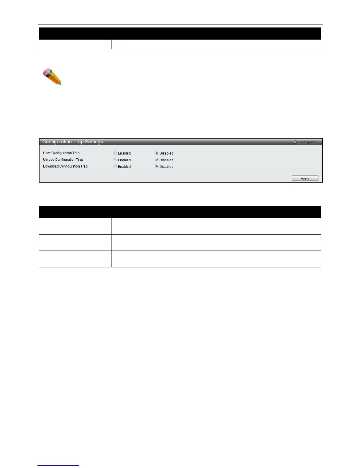
Configuration Trap Settings
This window is used to configure the trap settings when the configuration is saved, uploaded and downloaded.
To view this window, click System Configuration > Configuration Trap Settings, as shown below:
Figure 2-34 Configuration Trap Settings window
The fields that can be configured are described below:
Parameter Description
Save Configuration Trap
Use the drop-down menu to enable or disable sending the trap by the SNMP
agent when the configuration is saved in NVRAM.
Use the drop-down menu to enable or disable sending the trap by the SNMP
agent when successfully uploading configuration.
Use the drop-down menu to enable or disable sending the trap by the SNMP
agent when successfully downloading configuration.
Click the Apply button to accept the changes made.
Stacking (EI and SI Mode Only)
From firmware release v1.00 of this Switch, the Switch now supports switch stacking, where a set of six switches
can be combined to be managed by one IP address through TELNET, the GUI interface (web), the console port or
through SNMP. Each switch of this series has two stacking ports located at the rear of the device, which can be
used to connect other devices and make them stack together. After adding these stacking ports, the user may
connect these ports together using copper cables (also sold separately) in one of two possible topologies.
Duplex Chain – As shown in Figure 2-35, The Duplex Chain topology stacks switches together in a chain-link
format. Using this method, data transfer is only possible in one direction and if there is a break in the chain, then
data transfer will obviously be affected.
Duplex Ring – As shown in Figure 2-36, the Duplex Ring stacks switches in a ring or circle format where data can
be transferred in two directions. This topology is very resilient due to the fact that if there is a break in the ring, data
can still be transferred through the stacking cables between switches in the stack.

 Loading...


