xStack® DGS-3120 Series Layer 3 Managed Gigabit Ethernet Switch Web UI Reference Guide
44
custom subnet masks are allowed.
Gateway
IP address that determines where packets with a destination address outside the
current subnet should be sent. This is usually the address of a router or a host acting
as an IP gateway. If your network is not part of an intranet, or you do not want the
Switch to be accessible outside your local network, you can leave this field
Click the Apply button to accept the changes made.
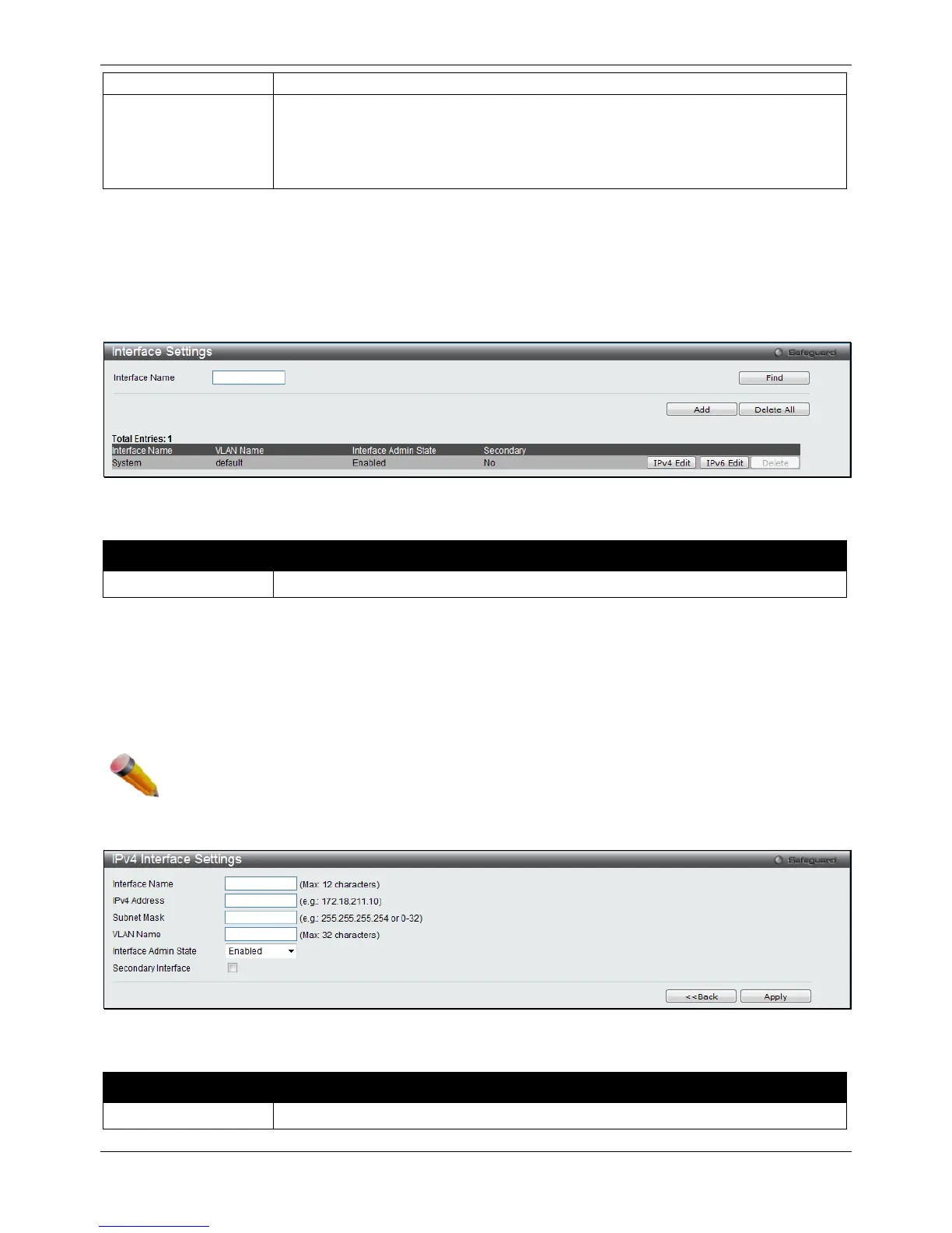
Interface Settings
Users can display the Switch’s current IP interface settings.
To view the following window, click Management > IP Interface > Interface Settings, as shown below:
Figure 3-8 Interface Settings window
The fields that can be configured are described below:
Parameter Description
Enter the name of the IP interface to search for.
Click the Find button to locate a specific entry based on the information entered.
Click the IPv4 Edit button to edit the IPv4 settings for the specific entry.
Click the Add button to add a new entry based on the information entered.
Click the Delete All button to remove all the entries listed.
Click the IPv6 Edit button to edit the IPv6 settings for the specific entry.
Click the Delete button to remove the specific entry.
NOTE: To create IPv6 interfaces, the user has to create an IPv4 interface then edit it to IPv6.
Click the Add button to see the following window.
Figure 3-9 IPv4 Interface Settings window
The fields that can be configured are described below:
Parameter Description
Enter the name of the IP interface being created.

 Loading...


