xStack® DGS-3120 Series Layer 3 Managed Gigabit Ethernet Switch Web UI Reference Guide
48
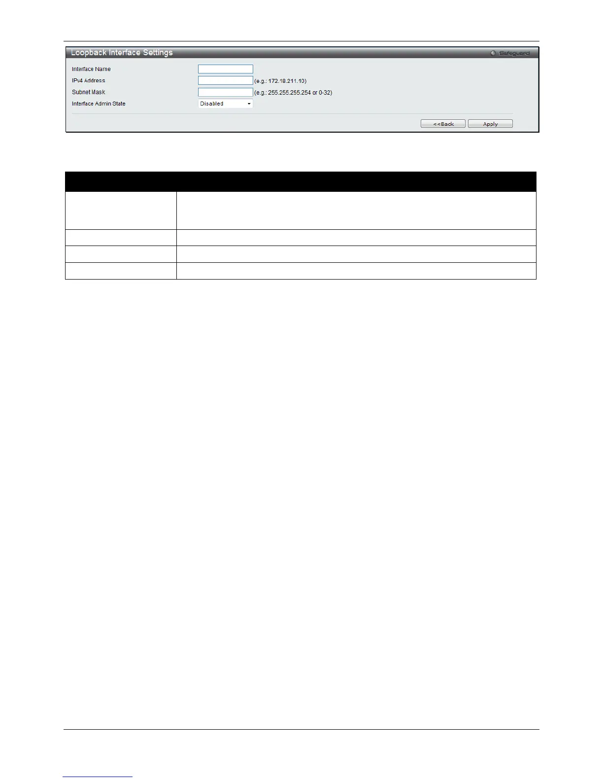
Figure 3-16 Loopback Interface Settings - Add/Edit window
The fields that can be configured are described below:
Parameter Description
Interface Name
The name of the loopback interface. The loopback interface has the same name
domain space as the regular interface. So the name can’t be a duplicate of any of the
Click the <<Back button to discard the changes made and return to the previous page.
Click the Apply button to accept the changes made for each individual section.
Management Settings
Users can stop the scrolling of multiple pages beyond the limits of the console when using the Command Line
Interface.
This window is also used to enable the DHCP auto configuration feature on the Switch. When enabled, the Switch
is instructed to receive a configuration file from a TFTP server, which will set the Switch to become a DHCP client
automatically on boot-up. To employ this method, the DHCP server must be set up to deliver the TFTP server IP
address and configuration file name information in the DHCP reply packet. The TFTP server must be up and
running and hold the necessary configuration file stored in its base directory when the request is received from the
Switch. For more information about loading a configuration file for use by a client, see the DHCP server and/or
TFTP server software instructions. The user may also consult the Upload Log File window description located in
the Tools section of this manual.
If the Switch is unable to complete the DHCP auto configuration, the previously saved configuration file present in
the Switch’s memory will be used.
This window also allows the user to implement the Switch’s built-in power saving feature. When power saving is
enabled, a port which has a link down status will be turned off to save power to the Switch. This will not affect the
port’s capabilities when the port status is link up.
Users can also configure Password Encryption on the Switch.
To view the following window, click Management > Management Settings, as shown below:

 Loading...


