xStack® DGS-3120 Series Layer 3 Managed Gigabit Ethernet Switch Web UI Reference Guide
460
For IPv6 only, enter a value between 1 and 6000. The default is 100.
Timeout Select a timeout period between 1 and 99 seconds for this Ping message to reach its
destination. If the packet fails to find the IP address in this specified time, the Ping
Source IPv4 Address
Enter the source IPv4 address. If the current switch has more than one IP address,
you can enter one of them to this field. When entered, this IPv4 address will be used
as the packets’ source IP address sent to the remote host, or as primary IP address.
Source IPv6 Address
Enter the source IPv6 address. If the current switch has more than one IPv6 address,
you can enter one of them to this field. When entered, this IPv6 address will be used
as the packets’ source IP address sent to the remote host, or as primary IP address.
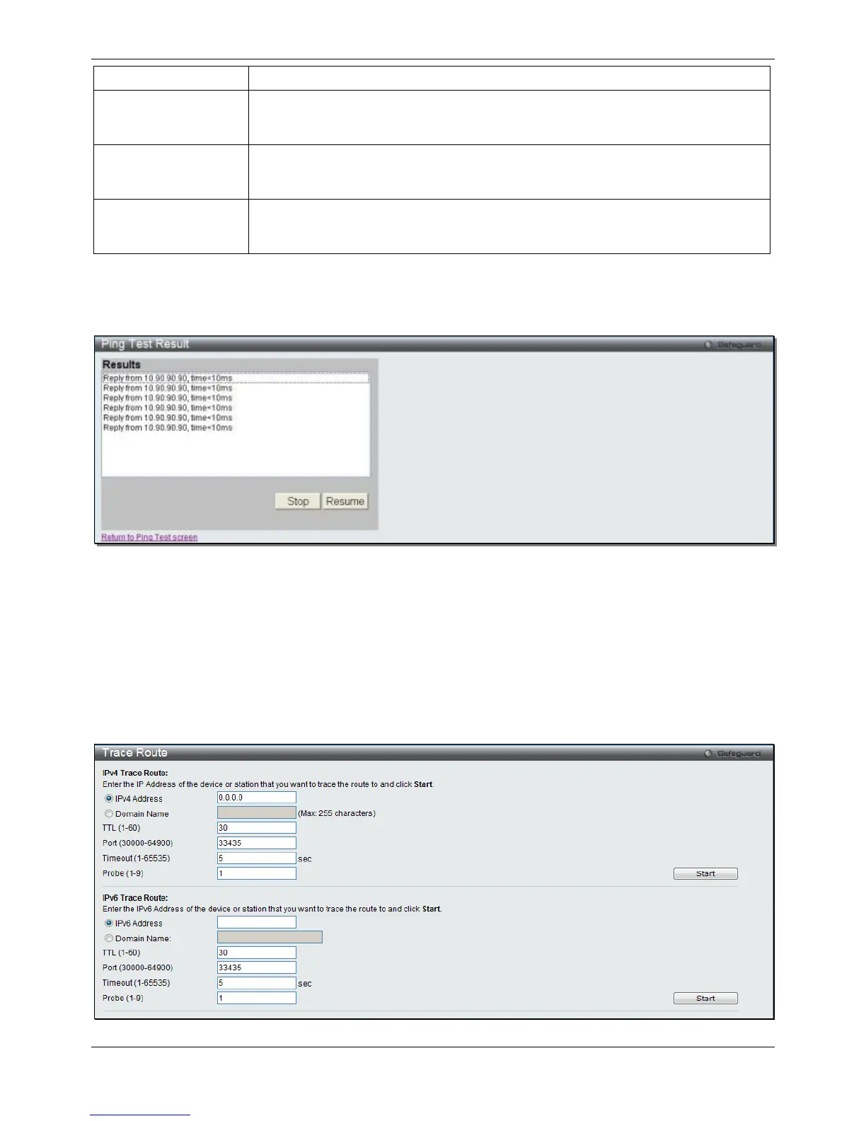
Click the Start button to initiate the Ping Test.
After clicking the Start button, the following window will appear:
Figure 11-26 Ping Test Result window
Click the Stop button to halt the Ping Test.
Click the Resume button to resume the Ping Test.
Trace Route
The trace route page allows the user to trace a route between the switch and a given host on the network.
To view this window, click Monitoring > Trace Route as shown below:
Figure 11-27 Trace Route window

 Loading...


