xStack® DGS-3120 Series Layer 3 Managed Gigabit Ethernet Switch Web UI Reference Guide
43
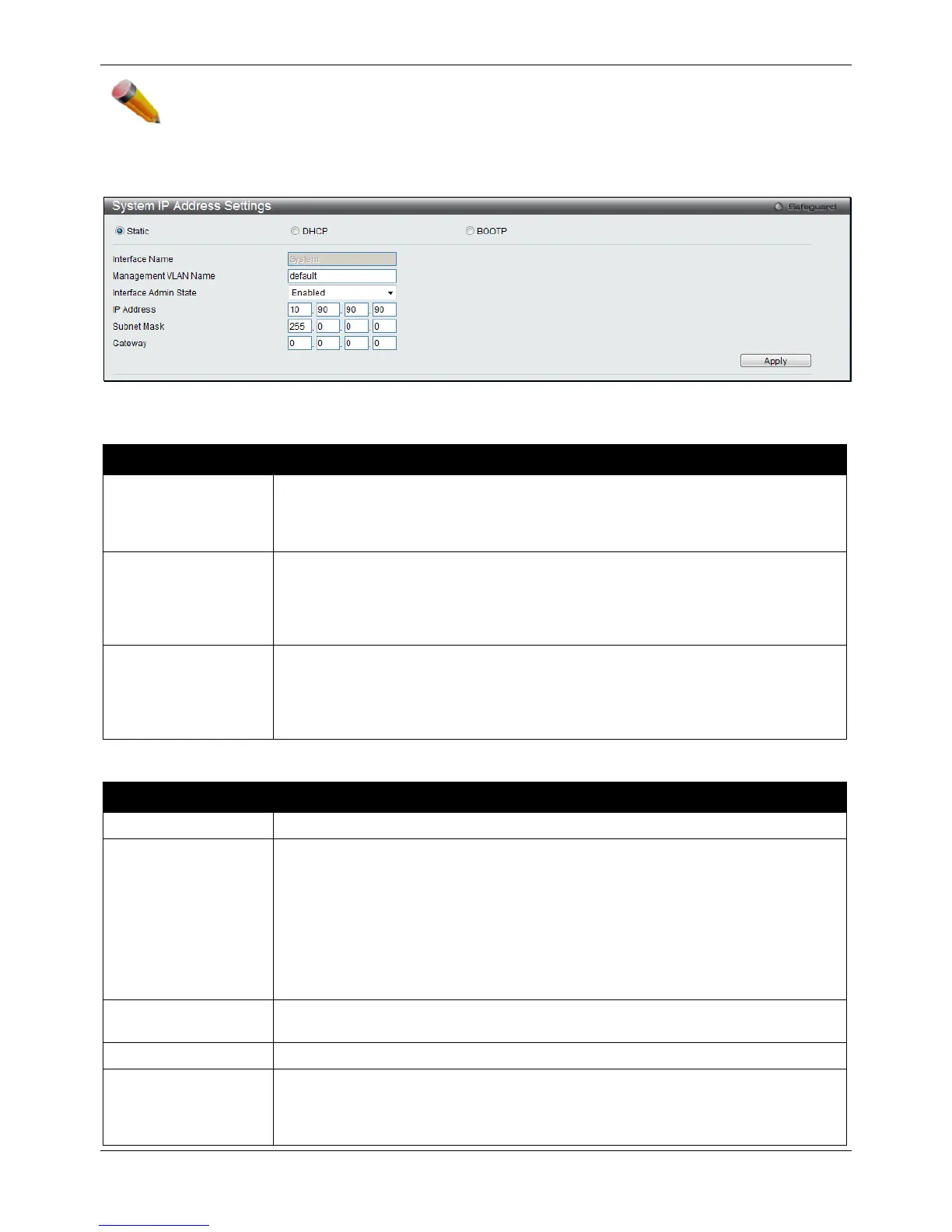
NOTE: The Switch’s factory default IP address is 10.90.90.90 with a subnet mask of 255.0.0.0 and a
default gateway of 0.0.0.0.
To view the following window, click Management > IP Interface > System IP Address Settings, as shown below:
Figure 3-7 System IP Address Settings window
The fields that can be configured are described below:
Parameter Description
Static
Allow the entry of an IP address, subnet mask, and a default gateway for the Switch.
These fields should be of the form xxx.xxx.xxx.xxx, where each xxx is a number
(represented in decimal form) between 0 and 255. This address should be a unique
address on the network assigned for use by the network administrator.
DHCP
The Switch will send out a DHCP broadcast request when it is powered up. The
DHCP protocol allows IP addresses, network masks, and default gateways to be
assigned by a DHCP server. If this option is set, the Switch will first look for a DHCP
server to provide it with this information before using the default or previously entered
BOOTP
The Switch will send out a BOOTP broadcast request when it is powered up. The
BOOTP protocol allows IP addresses, network masks, and default gateways to be
assigned by a central BOOTP server. If this option is set, the Switch will first look for a
BOOTP server to provide it with this information before using the default or previously
The following table will describe the fields that are about the System Interface.
Parameter Description
Display the System interface name.
Management VLAN
Name
This allows the entry of a VLAN name from which a management station will be
allowed to manage the Switch using TCP/IP (in-band via Web manager or TELNET).
Management stations that are on VLANs other than the one entered here will not be
able to manage the Switch in-band unless their IP addresses are entered in the
Trusted Host window (Security > Trusted Host). If VLANs have not yet been
configured for the Switch, the default VLAN contains all of the Switch’s ports. There
are no entries in the Trusted Host table, by default, so any management station that
can connect to the Switch can access the Switch until a management VLAN is
specified or Management Station IP addresses are assigned.
Interface Admin State
Use the drop-down menu to enable or disable the configuration on this interface. If
the state is disabled, the IP interface cannot be accessed.
This field allows the entry of an IPv4 address to be assigned to this IP interface.
Subnet Mask
A Bitmask that determines the extent of the subnet that the Switch is on. Should be of
the form xxx.xxx.xxx.xxx, where each xxx is a number (represented in decimal)
between 0 and 255. The value should be 255.0.0.0 for a Class A network,
255.255.0.0 for a Class B network, and 255.255.255.0 for a Class C network, but

 Loading...


