MECHANICAL GEARBOX CONTROL
1-4
©
200508
General
2
ΛΦ45/55 series
3
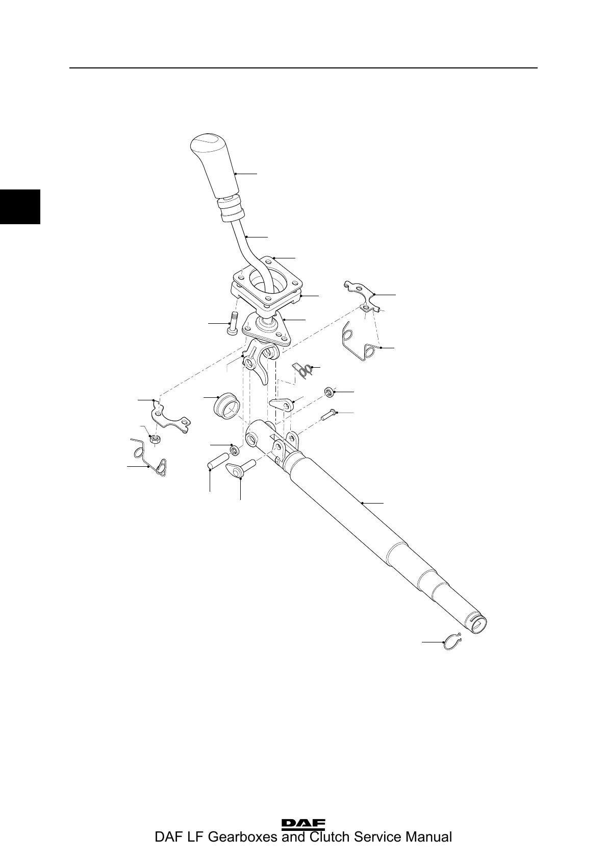
1.4 OVERVIEW DRAWING, GEAR LEVER UNIT
V3 00 568
1
2
3
4
5
6
7
8
9
10
11
14
15
10
16
17
6
5
13
12
19
18
1. Switch button 11. Clamping pin
2. Gear lever 12. Telescopic control rod
3. Attachment plate 13. Retainer clip
4. Vibration damper 14. Pawl
5. Spring holder 15. Axle
6. Centring spring 16. Plug
7. Bearing housing 17. Gear lever pawl
8. Spring 18. Attachment nut
9. Control rod pawl 19. Attachment bolt
10. Needle bearing
DAF LF Gearboxes and Clutch Service Manual
 Loading...