FC 300 Design Guide
How to Program
LCP read-out: Control Card I/O failure.
Replace the frequency converter or Contro l card.
The red LED on the Control Card is turned on.
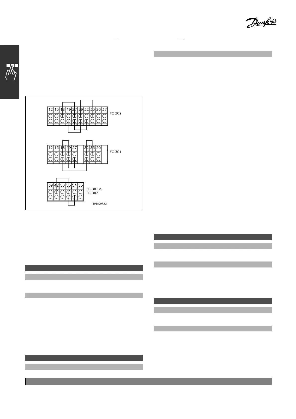
Te st plugs (connect the following terminals to each
other): 18 - 27 - 32; 19 - 29 - 33; 42 - 53 - 54
Select I nitialization [2 ] to reset all parameter
values to default settings, except for par. 15-03,
15-04, and 15-05. The frequency converter will
reset during the next power-up.
Par. 14 -22 will also revert to the default
setting Normal operation [0].
14-25 Trip Delay at Torque Limit
Option:
0-60s
*
60 s
Function:
Enter the torque limit trip delay in
seconds. When
theoutputtorquereachesthetorquelimits(par.
4-16 and 4-17), a warning is triggered. When the
torque limit warning has been
continuously present
for the period specified in this parameter, the
adjustable freq uency drive. Disab le the trip delay
by setting the parameter t
o60s=OFF.Thermal
VLT monitoring will still remain active.
14-26 Trip Delay at Inverter Fault
Option:
0-30s
*
5s
Function:
When the adjustable frequency drive detects
an overvoltage in the set time, tripping will
be affected after the set time.
" 14-3* Current Limit Control
The FC 3 00 series features an integral current
limit controller which is activated w hen the motor
current, and thus the torque , is higher than the
torque limits set in par. 4-16 and 4-17.
When the current limit is reached during motor
operation or regenerative operation, the adjustable
frequency drive will try to reduce torque below
the preset torque limits as quickly as possib le
without losing control of the motor.
While the current control is active, the adjustable
frequency drive can only be stopped by setting
a digital inp u t to Coast i nverse [2] or Coast and
reset inv. [3]. Any signal on terminals 18 to 33
will not be active until the adjustable frequency
drive is no longer near the current limit.
By using a digital input set to Coast inverse [2]
or Coast and reset inv. [3], the motor does
not use the ramp-down time, since the drive
is coasted. If a quick stop is necessary, use
the mechanical brake control function along
with an external electro-mechanic al brake
attached to the application.
14-30 Current Lim Cont, Proportional Gain
Option:
0 - 500%
*
100%
Function:
Enter the proportional gain value for the current
limit controller. Selection of a high value makes
the controller react faster. Too high a setting
leads to controller instability.
14-31 Current Lim Contr, Integration Time
Option:
0.002 - 2.000 s
*
0.020 s
Function:
Controls the current limit controller integration time.
Setting it to a lower value makes it reac t faster. A
setting too low lead s to controlle r instability.
*
default setting ()display text []value for use in communication via serial communication port
238
MG.33.B
6.22 - V LT is a registered Danfoss trademark

 Loading...


