Number (#) agrees to a digital input in slot C.
Number (#) agrees to a digital input in slot D.
Number (#) agrees to a digital input in slot E.
1=Time Channel1, 2=Time Channel2, 3=Time Channel3
Number (#) refers to a control word bit number.
Number (#) refers to the process data 1 bit number.
11.7.3 Default Functions of Programmable Inputs
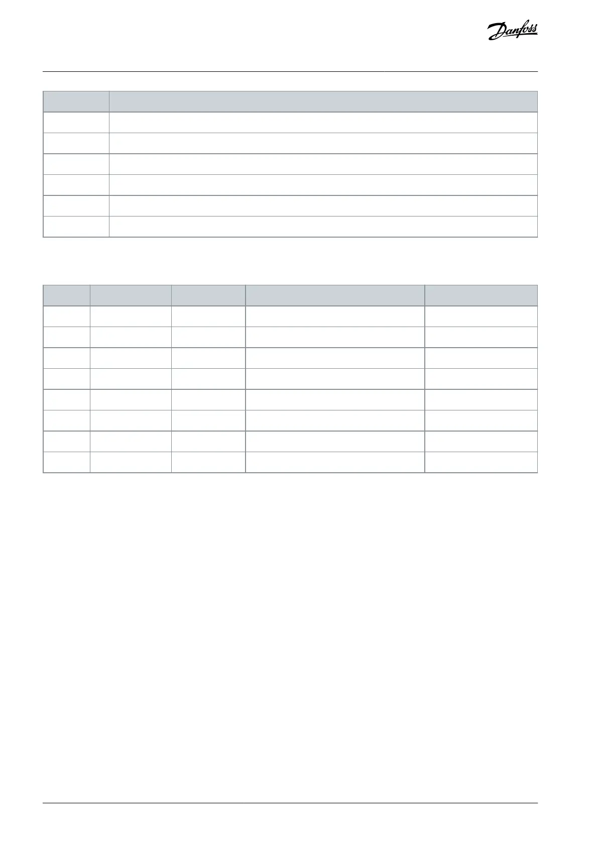
Table 131: Default Functions of the Programmable Digital and Analog Inputs
Preset Frequency Selection 0
Preset Frequency Selection 1
11.7.4 Digital Inputs
The parameters are functions that can be connected to a digital input terminal. The text DigIn Slot A.2 means the second input on
the slot A. It is also possible to connect the functions to time channels. The time channels work as terminals.
It is possible to monitor the statuses of the digital inputs and the digital outputs in the Multimonitoring view.
11.7.4.1 (ID 403) Control Signal 1 A
Location in the menu: P3.5.1.1
Use this parameter to select the digital input signal (Control Signal 1) that starts and stops the drive when the control place is I/O A
(FWD).
11.7.4.2 (ID 404) Control Signal 2 A
Location in the menu: P3.5.1.2
Use this parameter to select the digital input signal (Control Signal 2) that starts and stops the drive when the control place is I/O A
(REV).
11.7.4.3 (ID 434) Control Signal 3 A
Location in the menu: P3.5.1.3
Use this parameter to select the digital input signal (Control Signal 3) that starts and stops the drive when the control place is I/O A.
11.7.4.4 (ID 423) Control Signal 1 B
Location in the menu: P3.5.1.4
Use this parameter to select the digital input signal (Control Signal 1) that starts and stops the drive when the control place is I/O B.
AB298035655957en-000201 / DPD01083200 | Danfoss A/S © 2023.08
Parameter Descriptions
VACON® 100 FLOW
Application Guide
 Loading...


