1.
2.
3.
1.
2.
3.
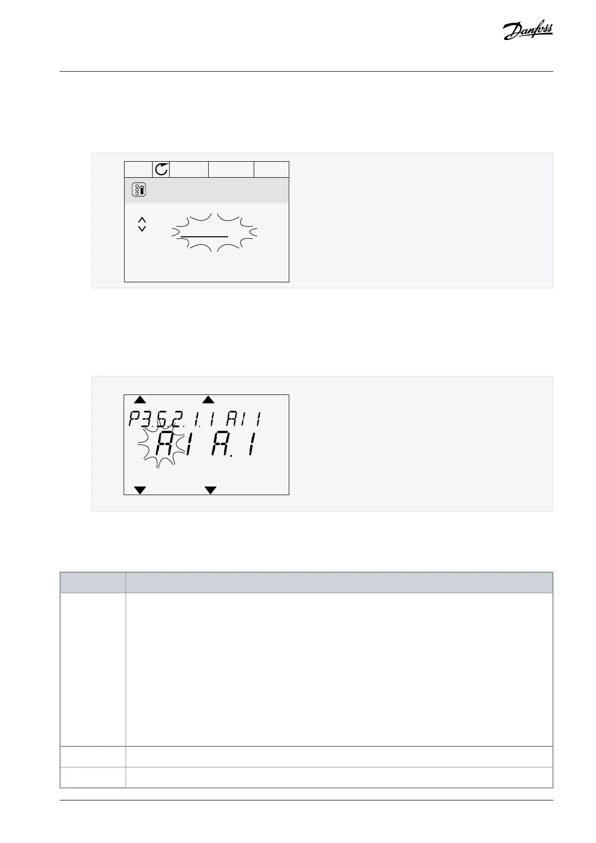
11.7.1.6 Programming of Analog Inputs in the Graphical Display
Procedure
To select the parameter, push the arrow button Right.
In the Edit mode, the value AnIN SlotA is underlined and blinks.
AI1 Signal Sel
AnIN SlotA .1
P3.5.2.1.1
To change the value to AnIN SlotC, push the arrow button Up. Accept the change with the [OK] button.
11.7.1.7 Programming of Analog Inputs in the Text Display
Procedure
To select the parameter, push the [OK] button.
In the Edit mode, the letter A blinks.
To change the value to C, push the arrow button Up. Accept the change with the [OK] button.
11.7.2 Descriptions of Signal Sources
Table 130: Descriptions of Signal Sources
Digital inputs:
Use this function to set a digital signal to be in a constant OPEN or CLOSED state. The manufacturer set some
signals so that they are always in the CLOSED state, for example parameter P3.5.1.15 (Run Enable). The Run Ena-
ble signal is always on if it is not changed.
# = 1: Always OPEN
# = 2–10: Always CLOSED
Analog inputs (used for testing purposes):
# = 1: Analog input = 0% of the signal strength
# = 2: Analog input = 20% of the signal strength
# = 3: Analog input = 30% of the signal strength, and so on
# = 10: Analog input = 100% of the signal strength
Number (#) agrees to a digital input in slot A.
Number (#) agrees to a digital input in slot B.
AB298035655957en-000201 / DPD01083 | 199Danfoss A/S © 2023.08
Parameter Descriptions
VACON® 100 FLOW
Application Guide
 Loading...


