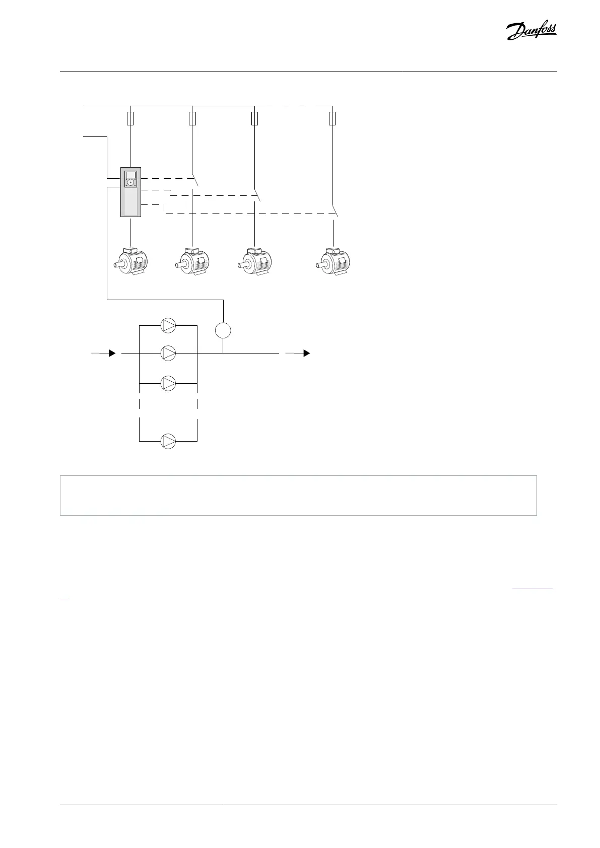
Illustration 88: Single Drive Configuration
11.17.2.2 Multidrive Configuration
The Multidrive modes (Multimaster and Multifollower) control a system that has the maximum 8 variable speed pumps. Each pump
is controlled by a drive. The internal PID controller of the drive controls all pumps. The drives use a communication bus (Modbus
RTU) for communication.
The figure shows the Multidrive configuration principle. See also the general electric diagram of a Multi-pump system in Illustration
20.
AB298035655957en-000201 / DPD01083 | 255Danfoss A/S © 2023.08
Parameter Descriptions
VACON® 100 FLOW
Application Guide

 Loading...

