Using the BC40xx™ Radio Base
Product Reference Guide 27
Using the BC40xx™ Radio Base
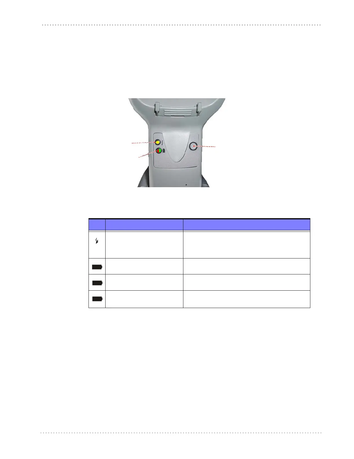
Base LEDs
LEDs on the Gryphon I Base provide information about the Base’s status, as shown in Figure
14.
Figure 14
YELLOW LED
RED LED —
GREEN LED
BUTTON
. Gryphon I Base LEDs
The following table describes the significance of each LED:
LED STATUS
Power on / Data
Yellow On = Base is powered
Yellow Blinking = Base receives data and
commands from the Host or the Reader.
Charging Red On = the Battery is in progress.
Charge completed Green On = the Battery is completely charged.
Charging + Charge completed
Red and Green Blinking together = the Reader is not
c
orrectly placed onto the Base.
See "Base Station Indications" on page 389 fo
r more specific details on the LEDs.
Base Button
The base contains a button, which is used primarily to perform a paging function. Pressing the
button causes a sound signal to be emitted by all scanners linked with this base, as long as the
scanner is awake (see "Powerdown Timeout" on page 164) and reception is enabled (s
ee "Sleep
Mode Timeout" on page 37).
The button can also be used to "force device connection" via the Datalogic Aladdin Software
tool (available for free down
load from the Datalogic website). See Aladdin for details.

 Loading...