Chapter 4 Operation Interface|VP3000
159
4-1-5 KPV-CE02 Function Display Instructions and Operation Flow
4-1-5-1 Function Display
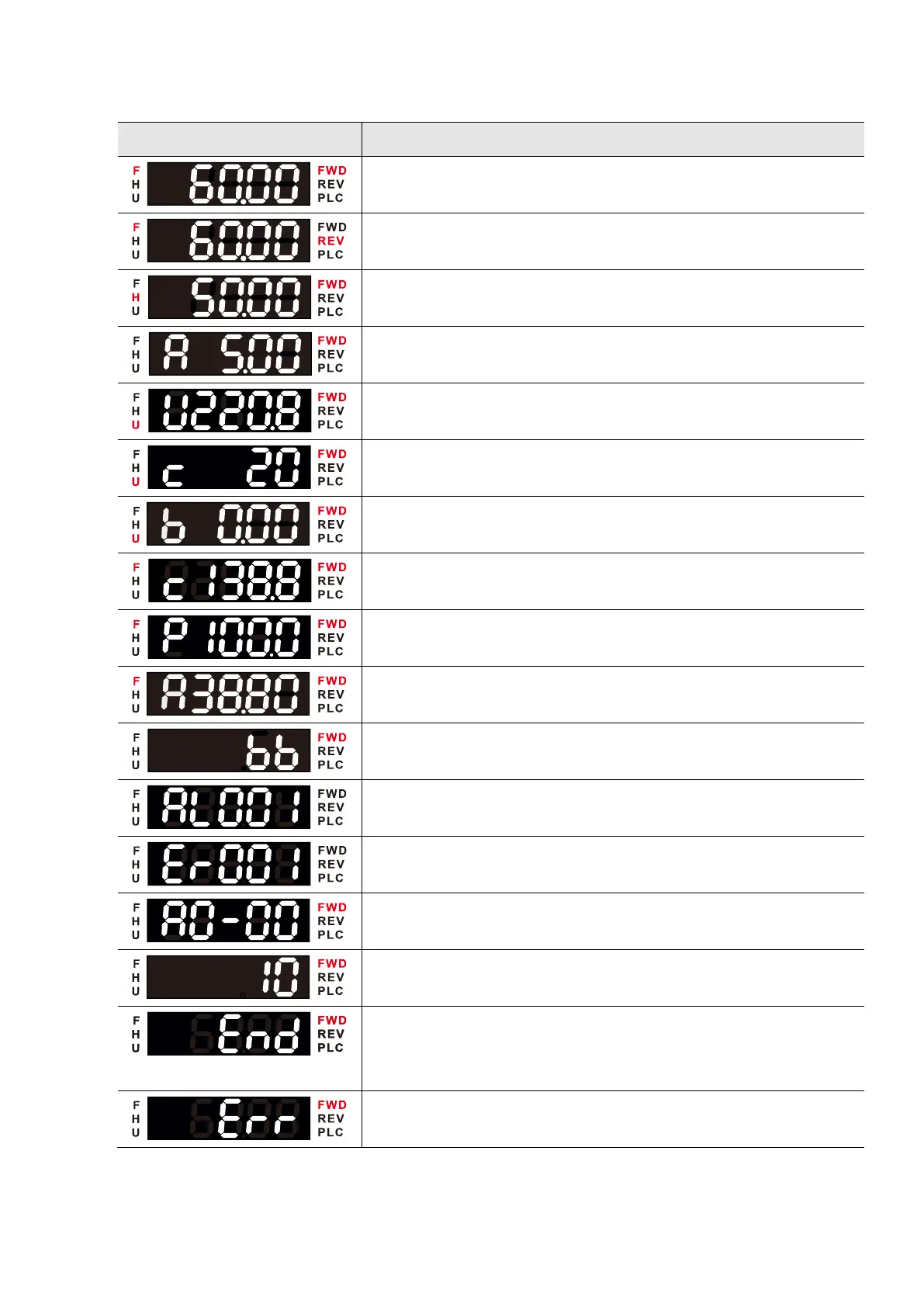
Display current set frequency and the drive is operating in FWD
direction
Display current set frequency and the drive is operating in REV
direction
Display the drive actual output frequency to the motor
Display the output current
Multi-function Display 1 The example on the left is Pr.o0-00 = 3
DC bus voltage
Multi-function Display 2 The example on the left is Pr.o0-01 = 1
Counter value
Multi-function Display 3 The example on the left is Pr.o0-02 = 44
PID Feedback
Display the frequency command of the main and auxiliary
frequency synthesis
Display the main frequency command
Display the auxiliary frequency command
Display current warning code
Display current error code
Display the selected parameter
Display the parameter value
If End message is displayed on the keypad (as shown on the
left), it means that the data has been accepted and stored
automatically in the internal memory
Displayed when the set data is not accepted, or the value
exceeds the setting range

 Loading...
