Chapter 10 Accessories | VP3000
665
10-3-2-1 Installation
During installation, pass the cable through at least one zero-phase reactor. Use a suitable
cable type (insulation class and wire section) so that the cable passes easily through the zero-
phase reactor. Do not pass the grounding cable through the zero-phase reactor; only pass the
motor wire through the zero-phase reactor.
With longer motor cables the zero-phase reactor can effectively reduce interference at the
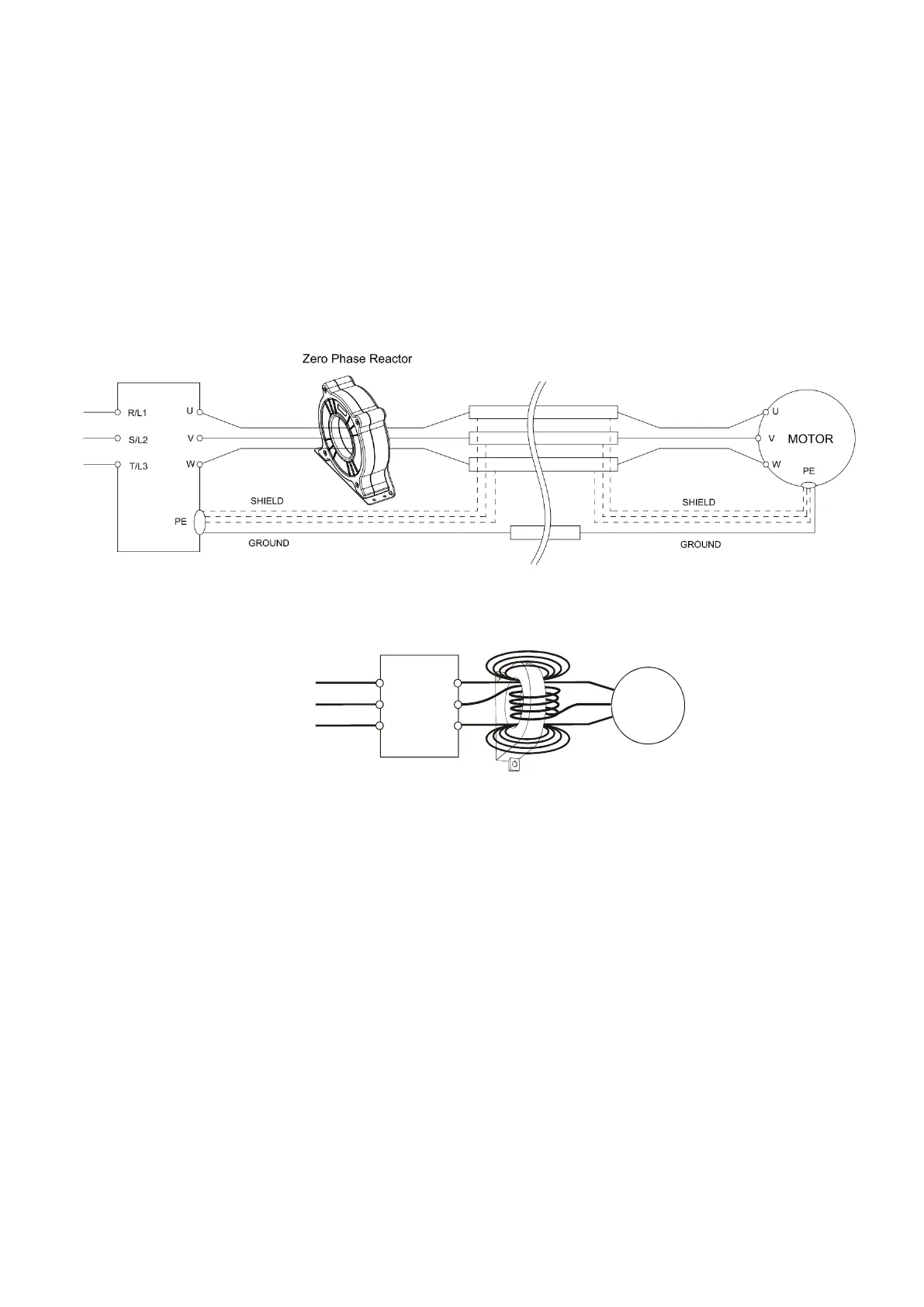
motor output. Install the zero-phase reactor as close to the output of the drive as possible. Figure A
shows the installation diagram for a single turn zero-phase reactor. If the wire diameter allows
several turns, Figure B shows the installation of a multi-turn zero-phase reactor. The more turns,
the better the noise suppression effect.
Figure A: Single turn wiring diagram for a shielding wire with a zero-phase reactor
Figure B: Multi-turn zero-phase reactor
10-3-2-2 Installation Notes
Install the zero-phase reactor at the output terminal of the frequency converter (U, V, W). After
the zero-phase reactor is installed, it reduces the electromagnetic radiation and load stress emitted
by the wiring of the frequency converter. The number of zero-phase reactors required for the drive
depends on the wiring length and the drive voltage.
The normal operating temperature of the zero-phase reactor should be lower than 85°C
(176°F). However, when the zero-phase reactor is saturated, its temperature may exceed 85°C
(176°F). In this case, increase the number of zero-phase reactors to avoid saturation. The
following are reasons that might cause saturation of the zero-phase reactors: the drive wiring is too
long, the drive has several sets of loads, the wiring is in parallel, or the drive uses high capacitance
wiring. If the temperature of the zero-phase reactor exceeds 85°C (176°F) during the operation of
the drive, increase the number of zero-phase reactors.

 Loading...
