Chapter 3 Electrical Wiring|VP3000
94
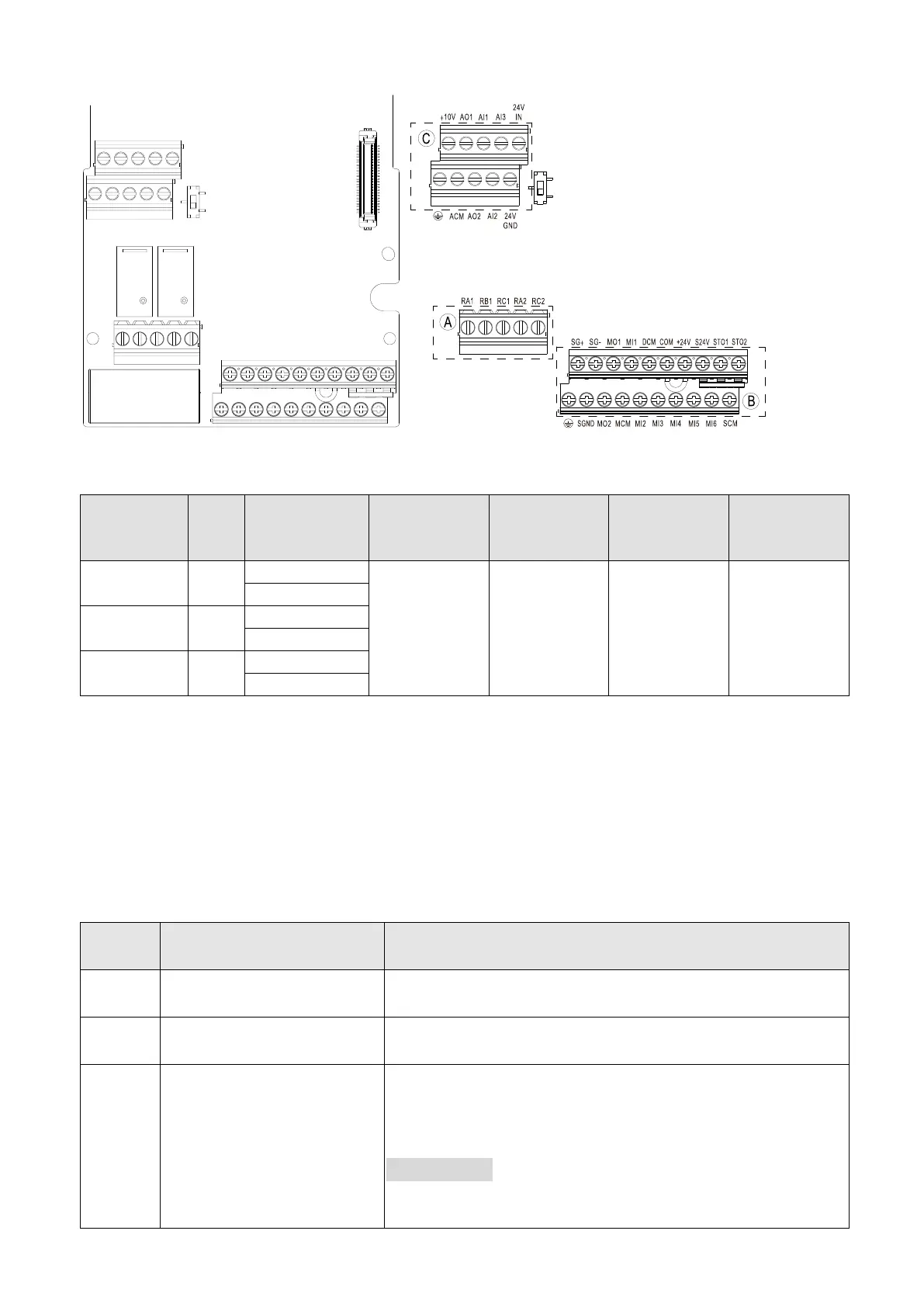
3-4-2 Terminal Specification
Figure 3-37
Tightening
Torque
(±10%))
5 kg-cm
(4.3 lb-in.)
(0.49 Nm)
Wiring Precautions:
⚫ In the figure above, the default for STO1, STO2 and +24V are short-circuited. Use the +24V
power supply of the safety function (as shown in section Ⓑ of above figure) for STO only. Do
NOT use it for other purposes. The default setting for +24V-COM is short-circuited and SINK
mode (NPN); refer to Chapter 3 Wiring for detail.
⚫ Tighten the wiring with slotted screwdriver: 3.5 mm (wide) x 0.4 mm (thick)
⚫ When wiring bare wires, ensure that they are perfectly arranged to go through the wiring holes.
+24 V
DC
± 10% 200 mA
For DI/O use
Digital control signal
common (Sink)
Multi-function input common terminal
Multi-function Input Selection
1–6
MI1–MI6 support three-wire / two-wire control
MI5 supports pulse input (basic input frequency 599 Hz)
Refer to the MI setting in Parameter Group G0 for MI1–MI6
function selection.
Source Mode:
ON: activation voltage ≥ 15 V
DC
OFF: cut-off voltage ≤ 5 V
DC

 Loading...
