EasyManuals Logo

Delta VP3000 Series User Manual

Delta VP3000 Series
714 pages
To Next Page IconTo Next Page
To Previous Page IconTo Previous Page
Page #650 background imageLoading...
Page #650 background image
Chapter 10 Accessories | VP3000
641
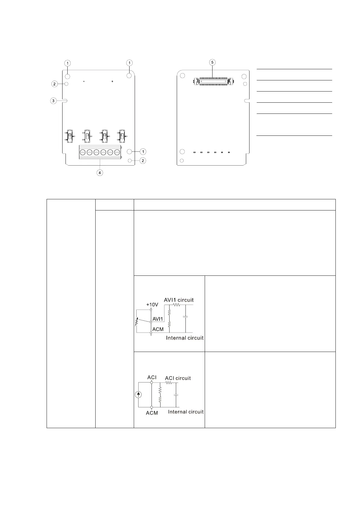
10-1-3 Extension Card for Analog Input/ Output
10-1-3-1 EMV-A22A -- Extension card for 2-point analog input/ 2-point analog output
âš« Product File
Figure 10-24
1. Screw fixing hole
2. Positioning hole
3. Fool-proof groove
4. Terminal block
5. AC motor drive
connection port
âš« Terminal Specification
Analog I/O
Card
Terminal
Descriptions
AI10, AI11
Refer to Parameter group G6 for analog input terminal and input mode
selection.
There are two sets of AI port, SSW3 (AI10) and SSW4 (AI11), which can
be switched to Voltage or Current mode.
Voltage mode: Input 0–10 V
Current mode: Input 0–20 mA / 4–20 mA
Analog voltage frequency
command
Figure 10-25
Impedance: 20 kΩ
Range: 0–10 V = 0
AI10, AI11 Switch, default is 0–10 V
Analog current frequency
command
Figure 10-26
Impedance: 250 Ω
Range: 0–20 mA / 4–20 mA = 0
AI10, AI11 Switch, default is 0–10 V

Table of Contents

Questions and Answers:

Question and Answer IconNeed help?

Do you have a question about the Delta VP3000 Series and is the answer not in the manual?

Delta VP3000 Series Specifications

General IconGeneral
BrandDelta
ModelVP3000 Series
CategoryServo Drives
LanguageEnglish

Related product manuals