Chapter 3 Electrical Wiring|VP3000
96
4. Analog input can be read and written normally
5. When Digital I/O uses external input, the 24 V
DC
power
supplies normally (refer to external power Sink / Source
mode)
⚫ Input voltage range: 24V ± 5%
NOTE: the following functions cannot work
Relay output, I/O extension card and PLC function
24V auxiliary power input
common
Default short circuit of STO1-STO2-S24V (disable STO function). Only provide Source
trigger mode.
Built-in STO/SIL3 according to IEC61800-5-2, EN 61508 SIL3/ EN ISO 13849-1 PLe
STO1–SCM; STO2–SCM ON: voltage ≥ 15 V
DC
STO1–SCM; STO2–SCM OFF: voltage ≤ 5 V
DC
S24V–SCM only use for STO1 and STO2 circuit
STO1, STO2 and S24V common
PIN1, 2, 7, 8: Reserve PIN3, 6: SGND PIN4: SG- PIN5: SG+
NOTE: When the drive input side is connected to USB (not connected to the RST main power
supply), it mainly provides parameter reading, writing and software burning function, other
functions (including control terminals) cannot be used.
3-4-3 Calendar Battery Installation
To ensure the calendar function is normal, check and install the CR2032 battery and adjust the time
before use. Follow the following steps to install the battery:
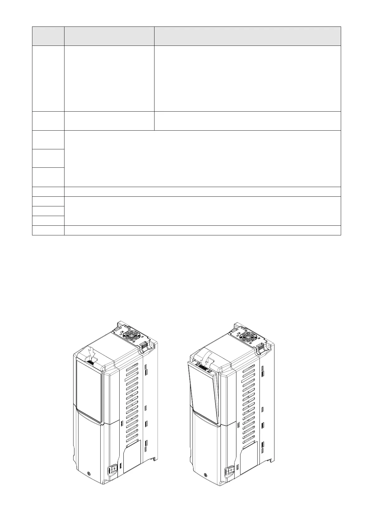
1. Press and hold the top tab of the keypad panel and pull forward (outward) to remove it.

 Loading...
